
Component · Controller
ESP32
The ESP32 is a fast dual-core microcontroller with built-in Wi-Fi and Bluetooth—an Arduino you can talk to wirelessly. What it does and when to pick it.
What it is
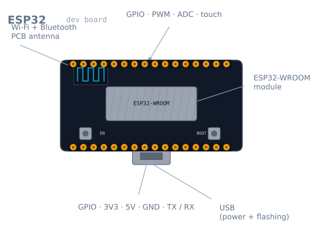
The ESP32 is a microcontroller that feels like an Arduino with a radio bolted on and the brakes taken off. It has a dual-core 32-bit processor that runs many times faster than an Uno, far more memory, and—the headline feature—Wi-Fi and Bluetooth built in. That combination is why it dominates hobby robotics and IoT: a robot can host a web page to control itself, stream sensor data to your phone, or take commands over Bluetooth, all from one cheap chip.
Crucially, you program it with the same Arduino IDE and language you may already know. The learning you did on an Uno transfers directly; you simply gain connectivity and headroom.
How it works
At its heart are two Xtensa CPU cores clocked up to 240 MHz. Having two cores matters for robots: one core can run your control loop with steady timing while the other handles Wi-Fi, so networking never stalls the wheels. Around the CPU sit the usual microcontroller peripherals—GPIO, PWM channels, multiple ADCs, I²C, SPI, UART—plus the radio.
The most important practical fact is the voltage: the ESP32 runs at 3.3 V logic, not the Uno’s 5 V. Its pins are not 5 V tolerant. A 5 V sensor output—like the Echo pin of an HC-SR04—must be dropped to 3.3 V before it touches an ESP32 pin, or you risk damage. This one difference trips up almost everyone moving from an Uno.
When to use it
Reach for an ESP32 when your robot needs to be wireless—remote control, telemetry, a browser dashboard—or when it needs compute an 8-bit board can’t manage, like processing more sensors or running lightweight on-device logic. The ESP32-CAM variant adds a camera, opening up simple vision projects.
Stick with an Arduino Uno when you are learning the fundamentals, when 5 V tolerance makes wiring safer, or when the project is simple and offline—driving a couple of motors around a line doesn’t need Wi-Fi.
Wiring and gotchas
- It is 3.3 V, and not 5 V tolerant. Level-shift any 5 V signal before it reaches a GPIO. This is the single most common way beginners damage an ESP32.
- Wi-Fi plus motors can brown out the board. The radio draws sharp current spikes; sharing a weak supply with motors causes resets. Power motors separately through a motor driver and give the ESP32 a stable 3.3 V rail.
- Not every pin is free. Several GPIOs are input-only, tied to boot behaviour, or connected to internal flash. Check a pinout before assigning pins, or the board won’t boot.
- ADC quirks. One of the two ADCs is unavailable while Wi-Fi is active, and the readings are less linear than an Uno’s—calibrate if you need accuracy.
The pins you must not use
An ESP32 has around 34 GPIOs and this is genuinely misleading, because a significant number of them are unusable, conditionally usable, or will stop the board booting. This table is the one thing worth reading before wiring anything.
| Pins | Status | Why |
|---|---|---|
| GPIO 6–11 | Never use | Connected to the internal SPI flash. Using them bricks the boot |
| GPIO 0 | Boot mode | Must be HIGH at reset, or the board enters flash mode |
| GPIO 2 | Boot mode | Must be floating or LOW at reset |
| GPIO 12 | Boot mode | Must be LOW at reset — a pull-up here stops the board booting |
| GPIO 15 | Boot mode | HIGH at reset silences the boot log |
| GPIO 34–39 | Input only | No output driver, and no internal pull-ups either |
| GPIO 1, 3 | Serial (TX0/RX0) | Used by the USB programmer |
The safest general-purpose pins on a standard 30-pin dev board are GPIO 4, 5, 13, 14, 16, 17, 18, 19, 21, 22, 23, 25, 26, 27, 32, 33. Start there and you will avoid every trap above.
The boot-mode pins are the most confusing failure, because the board works perfectly until you attach something. A pull-up resistor on GPIO 12 — entirely reasonable for a button — means the board simply will not start, with no error and no serial output.
The input-only pins catch people differently: GPIO 34–39 have no internal pull-up or pull-down, so a button on one of them floats and reads randomly. They need an external resistor.
3.3 V, and what that costs you
The ESP32’s pins are not 5 V tolerant, and this is the single most common way people damage one. Any 5 V signal needs handling:
| Situation | Solution |
|---|---|
| 5 V sensor output → ESP32 input | Resistor divider (1 kΩ / 2 kΩ) or a level shifter |
| ESP32 output → 5 V device input | Usually fine — most 5 V logic reads 3.3 V as HIGH |
| Bidirectional I²C between 5 V and 3.3 V | A proper bidirectional level shifter (BSS138-based) |
| 5 V I²C device with its own 3.3 V pull-ups | Often works directly — check where the pull-ups go |
The asymmetry is worth internalising: outputs are usually safe, inputs usually are not. An HC-SR04’s Echo pin is the classic case — it drives a full 5 V into a pin rated for 3.6 V absolute maximum.
The ADC problem
The ESP32’s ADC is the weakest part of the chip, and pretending otherwise wastes hours.
ADC2 does not work while Wi-Fi is active. The radio uses it. Any analogRead on an ADC2
pin returns garbage or blocks the moment Wi-Fi connects — and since a wireless robot is the
whole reason to use an ESP32, this rules ADC2 out almost entirely. Use ADC1 only:
GPIO 32–39.
The response is not linear. The 12-bit ADC is noticeably non-linear at both ends, and
readings below about 0.1 V and above roughly 3.1 V are compressed. The chip has factory
calibration data that the ESP-IDF’s esp_adc_cal functions apply for you; the Arduino
analogRead does not use it by default.
| Attenuation | Usable input range |
|---|---|
ADC_0db |
0–1.1 V |
ADC_2_5db |
0–1.5 V |
ADC_6db |
0–2.2 V |
ADC_11db (default) |
0–3.3 V, least linear |
If you need real accuracy from an analog sensor, the pragmatic answer is an external I²C ADC such as an ADS1115. It costs a few dollars and removes the whole problem.
Powering it without brownouts
This is where ESP32 robot projects most often fail, and the cause is not obvious.
The radio does not draw a steady current — it draws it in bursts. A transmit burst can
be 500 mA for a few hundred microseconds against a 40–80 mA average. A supply that
measures fine on a multimeter can still sag on those spikes, and the ESP32 responds by
resetting with a Brownout detector was triggered message.
| Rule | Why |
|---|---|
| Supply at least 500 mA, ideally 1 A | Peak, not average, is what matters |
| Put 100 µF or more near the board’s 3.3 V pin | Local charge to cover the burst |
| Never share a rail with motors | Motor inrush plus radio burst is a guaranteed reset |
| Use a good USB cable | A thin cable’s resistance turns a burst into a brownout |
| Prefer the 5 V pin over the 3.3 V pin | The onboard regulator handles the transients |
That last point is worth stating plainly: feed 5 V into the VIN/5V pin and let the
board’s regulator make 3.3 V. Injecting 3.3 V directly bypasses the regulator and its
smoothing, which is exactly what you want it for.
Two cores, and how to actually use them
The dual core is the ESP32’s real advantage for robots, and the Arduino framework hides it —
your loop() runs on core 1, and the Wi-Fi stack runs on core 0.
You can pin a task to a core explicitly:
void controlLoop(void *param) {
  const TickType_t period = pdMS_TO_TICKS(10);   // exactly 100 Hz
  TickType_t last = xTaskGetTickCount();
  for (;;) {
    readSensors();
    updatePid();
    driveMotors();
    vTaskDelayUntil(&last, period);              // no drift, unlike delay()
  }
}

void setup() {
  xTaskCreatePinnedToCore(
    controlLoop, "control", 4096, nullptr,
    2,          // priority above the default
    nullptr,
    1);         // core 1 — leave core 0 for Wi-Fi
}
This is the pattern that makes an ESP32 genuinely good for robots rather than just
connected: a control loop with hard timing on one core, and a web server on the other that
cannot stall it. vTaskDelayUntil is the important detail — unlike delay(), it compensates
for however long the loop body took, so the period stays exactly 10 ms.
Troubleshooting
| Symptom | Likely cause | Fix |
|---|---|---|
Brownout detector was triggered |
Supply sagging on radio bursts | Stiffer supply, 100 µF locally, feed 5 V not 3.3 V |
| Board will not boot at all | Something pulling GPIO 0, 2 or 12 | Free the boot-mode pins |
analogRead returns garbage on Wi-Fi |
Using an ADC2 pin | Move to ADC1: GPIO 32–39 |
| A pin never goes high | GPIO 34–39 are input only | Use a different pin |
| Button on GPIO 35 reads randomly | No internal pull-ups on 34–39 | Add an external resistor |
| Upload fails, needs the BOOT button | Auto-reset circuit missing on the clone | Hold BOOT while upload begins, or add a 10 µF cap on EN |
| Random resets under motor load | Shared power rail | Separate supplies, common ground |
| Sensor damaged after wiring | 5 V into a 3.3 V pin | Level shift — and check the pin still works |
| Wi-Fi drops when motors run | Radio interference or supply sag | Move the antenna away from motor leads; decouple |
ESP32 or Arduino Uno?
| Uno | ESP32 | |
|---|---|---|
| Speed | 16 MHz, 8-bit | Up to 240 MHz, dual-core 32-bit |
| SRAM | 2 KB | 520 KB |
| Logic | 5 V, forgiving | 3.3 V, unforgiving |
| Wireless | None | Wi-Fi and Bluetooth |
| Pin traps | Almost none | Several that stop the board booting |
| Learning curve | Everything works first time | Read the pinout before wiring anything |
Both use the same language and IDE, which is the point — the transition costs you almost nothing in code and quite a lot in wiring discipline.
The honest recommendation: learn on an Uno, build on an ESP32. The Uno’s 5 V tolerance and complete absence of pin traps mean your early mistakes are recoverable. Once you know what a control loop is and why grounds must be common, the ESP32 gives you fifteen times the clock speed, 260 times the memory, and a radio, for about the same money.
The ESP32-CAM variant is worth knowing separately: it adds a camera and an SD slot for a few dollars, and it is the cheapest route into robot vision by a wide margin — at the cost of having almost no free GPIO left.
Explore the graph
Used in these builds
Projects, learning paths, and simulators that include the ESP32.
Compare
Alternatives
Questions
ESP32 FAQ
What is the ESP32?
The ESP32 is a low-cost microcontroller with a dual-core processor and built-in Wi-Fi and Bluetooth. Think of it as an Arduino that is much faster and can talk to networks and phones wirelessly, which is why it powers most connected robotics and IoT projects.
What is an ESP32 used for?
It is used wherever a project needs wireless connectivity or more processing than an 8-bit board can offer: Wi-Fi-controlled robots, web-based dashboards, Bluetooth remote control, sensor nodes that report to the cloud, and camera projects using the ESP32-CAM variant.
Is the ESP32 better than the Arduino Uno?
On raw specs, yes—it is far faster, has more memory, and includes wireless the Uno lacks. But the Uno is 5 V and more forgiving of wiring mistakes, while the ESP32 is 3.3 V and less tolerant. For learning basics the Uno is gentler; for connected or compute-heavy robots the ESP32 wins.
What is the difference between Arduino and ESP32?
Arduino usually means an 8-bit, 5 V, single-core board with no radio. The ESP32 is a 32-bit, 3.3 V, dual-core board with Wi-Fi and Bluetooth built in. Confusingly, you program both with the Arduino IDE, so 'Arduino' can mean the language and tools as well as the classic boards.
Does the ESP32 use C or C++?
The ESP32 is programmed in C++ (with plenty of C) using the Arduino framework or Espressif's own ESP-IDF. If you have written Arduino sketches, the language and structure carry straight over—you mostly just gain Wi-Fi, Bluetooth, and more pins to work with.
Can you program the ESP32 with the Arduino IDE?
Yes. After adding the ESP32 board package to the Arduino IDE's board manager, you write and upload sketches exactly as you would for an Uno, and existing libraries largely work. This is the easiest way to start, before moving to ESP-IDF for advanced features.
Further reading