
Component · Driver
L298N Motor Driver
The L298N is the dual H-bridge that lets a microcontroller drive two DC motors forward and back. How an H-bridge works, how to wire it, and its real limits.
What it is
The L298N is a dual H-bridge motor driver—the muscle between a microcontroller’s delicate logic pins and a motor that wants far more current than those pins can supply. A microcontroller pin can source only a few tens of milliamps; even a small geared DC motor pulls hundreds. The L298N takes low-power direction and speed signals from the board and switches a separate, higher-current motor supply to match. It drives two motors independently, which is exactly what a two-wheeled robot needs.
It is dated—an efficient MOSFET driver like a TB6612FNG or DRV8833 runs cooler and wastes less voltage—but the L298N is everywhere, cheap, rugged, and the module most robotics kits ship with, so it is worth understanding well.
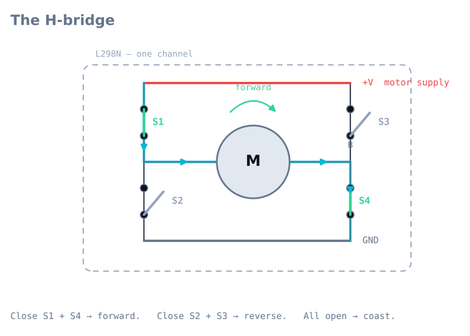
How an H-bridge works
An H-bridge is four switches arranged around the motor in an “H”. Close the top-left and bottom-right switches and current flows one way—the motor spins forward. Close the opposite pair and current reverses—the motor spins backward. That is the whole trick: an H-bridge lets you reverse a motor without rewiring it.
You control each motor with three signals:
- Two direction pins (IN1/IN2) pick forward, reverse, or brake.
- One enable pin (ENA), fed a PWM signal, sets speed by switching the bridge on and off quickly. Full-on PWM is full speed; 50% duty is roughly half.
Feed the enable pin the output of a control loop and you can hold a target speed or steer a robot smoothly instead of lurching between stop and full-tilt.
When to use it
Reach for an L298N—or any H-bridge—any time a microcontroller must drive a brushed DC motor, which is nearly every wheeled robot. Its 2 A per channel comfortably handles the small yellow gear motors used in line followers and rovers.
Choose a MOSFET-based driver instead when efficiency and battery life matter, when your motors are small (the L298N’s voltage drop wastes a lot on a 6 V motor), or when you want the driver to run cool without a heatsink.
Wiring and gotchas
- Two supplies, one ground. The motor battery feeds the motor supply pin; 5 V logic feeds the logic side. Their grounds must be tied together or the control signals have no reference—a classic silent failure.
- It steals ~2 V. The older BJT output stage drops roughly 2 V before the motor sees anything. Give a 6 V motor about 8 V of supply to run at full speed.
- It gets hot. At sustained current the chip needs its heatsink. If motors weaken during a run, check the temperature.
- Mind the on-board 5 V regulator jumper. Many modules can power the logic side from the motor supply—handy, but only up to ~12 V in. Above that, remove the jumper and supply 5 V separately or you will cook the regulator.
Pinout
The red L298N module everyone means has three terminal blocks and two pin headers.
| Group | Marking | What it does |
|---|---|---|
| Power | +12V |
Motor supply, 5–35 V. The name is misleading — it is whatever your motors want |
| Power | GND |
Ground. Must be shared with the microcontroller |
| Power | +5V |
Output when the regulator jumper is on; input when it is off |
| Motor A | OUT1, OUT2 |
The two motor terminals for channel A |
| Motor B | OUT3, OUT4 |
The two motor terminals for channel B |
| Control | ENA |
Channel A enable. Jumpered high by default — remove the jumper to PWM it |
| Control | IN1, IN2 |
Channel A direction |
| Control | IN3, IN4 |
Channel B direction |
| Control | ENB |
Channel B enable. Same jumper |
The two little jumpers on ENA and ENB are the reason so many first attempts have
direction control but no speed control: while they are fitted, the channel is permanently
enabled and PWM does nothing. Pull them off and wire those pins to PWM-capable outputs.
The third jumper, next to the power block, enables the onboard 5 V regulator.
The truth table
Three signals per motor, and six meaningful combinations. This table is the whole control interface.
| ENA | IN1 | IN2 | Motor A does | Notes |
|---|---|---|---|---|
| LOW | × | × | Coasts | Outputs are high-impedance; the motor freewheels |
| PWM | HIGH | LOW | Forward at duty | The normal driving state |
| PWM | LOW | HIGH | Reverse at duty | |
| HIGH | HIGH | HIGH | Brakes | Both terminals tied high — the motor shorts through itself |
| HIGH | LOW | LOW | Brakes | Both tied low — same effect |
| HIGH | HIGH | LOW | Full speed forward | What the fitted ENA jumper gives you |
Brake and coast are genuinely different, and the difference matters more than people expect. Coasting lets the robot roll on; braking shorts the motor’s own back-EMF through the bridge, which dumps the rotational energy as heat and stops it far more sharply. A line follower that overshoots every junction is often one that coasts when it should brake.
Wiring it to an Arduino
| L298N | Arduino Uno | Note |
|---|---|---|
ENA |
Pin 9 | Must be PWM-capable (3, 5, 6, 9, 10, 11 on an Uno) |
IN1 |
Pin 8 | Any digital pin |
IN2 |
Pin 7 | Any digital pin |
IN3 |
Pin 5 | Any digital pin |
IN4 |
Pin 4 | Any digital pin |
ENB |
Pin 3 | Must be PWM-capable |
GND |
GND | The connection everything depends on |
+12V |
Motor battery + | Not the Arduino’s Vin |
+5V |
— | Only if you are powering the Arduino from the L298N |
The 5 V regulator jumper, decided properly
| Jumper | +5V pin is |
Use when |
|---|---|---|
| Fitted | An output — the onboard regulator makes 5 V from the motor supply | Motor supply is 7–12 V and you want one battery for everything |
| Removed | An input — you must feed it 5 V | Motor supply is above 12 V, or below about 7 V |
Above roughly 12 V the linear regulator has to burn the difference as heat and it will cook. Below about 7 V it cannot maintain 5 V, and the logic browns out as the motors load the pack. Both failures look like random resets.
Minimal working code
const int ENA = 9, IN1 = 8, IN2 = 7;
const int ENB = 3, IN3 = 5, IN4 = 4;

void setup() {
  for (int p : {ENA, IN1, IN2, ENB, IN3, IN4}) pinMode(p, OUTPUT);
}

// speed: -255..255. Negative is reverse, 0 coasts.
void driveA(int speed) {
  digitalWrite(IN1, speed > 0);
  digitalWrite(IN2, speed < 0);
  analogWrite(ENA, abs(constrain(speed, -255, 255)));
}

void brakeA() {
  digitalWrite(IN1, HIGH);
  digitalWrite(IN2, HIGH);
  analogWrite(ENA, 255);
}

void loop() {
  driveA(180); delay(1500);   // forward
  brakeA();    delay(500);    // stop hard
  driveA(-180); delay(1500);  // reverse
  driveA(0);   delay(500);    // coast
}
Note driveA(0) coasts rather than brakes — setting the duty to zero disables the bridge.
If you want a hard stop you must ask for one.
The 2 V problem, quantified
The L298N’s output stage is built from bipolar transistors, and each conducting pair drops voltage. The datasheet gives a total saturation drop of roughly 1.8 V at 1 A and up to about 2.7 V at 2 A. That voltage never reaches the motor; it becomes heat in the chip.
The consequences are worth seeing as numbers:
| Motor supply | Motor actually sees | Fraction lost |
|---|---|---|
| 6 V | ~4 V | 33% |
| 7.4 V (2S Li-ion) | ~5.4 V | 27% |
| 9 V | ~7 V | 22% |
| 12 V | ~10 V | 17% |
On a 6 V motor running from 6 V, a third of your battery is heating a chip. This is the whole reason the L298N feels weak on small robots — and why a 6 V motor wants roughly 8 V of supply behind this driver.
It is also a thermal problem. At 1 A per channel with both motors running, the chip is dissipating around 4 W. The little heatsink handles that only with airflow, and a current-limited stall will push it into thermal shutdown — which presents as motors that fade out mid-run and recover after a pause.
Troubleshooting
| Symptom | Likely cause | Fix |
|---|---|---|
| Nothing moves, wiring looks right | No common ground | Tie L298N GND to Arduino GND — this is the classic silent failure |
| Direction works, speed does not | ENA/ENB jumpers still fitted |
Remove them and wire the pins to PWM outputs |
| Speed control is on/off only | Enable pin is not on a PWM-capable pin | Use 3, 5, 6, 9, 10 or 11 on an Uno |
| Motors weak, driver hot | The ~2 V drop plus thermal load | Raise the supply, or move to a MOSFET driver |
| Motors fade out during a run | Thermal shutdown | Heatsink and airflow; reduce continuous current |
| Arduino resets when motors start | Shared supply sagging | Separate motor battery; only ground is common |
| Regulator gets very hot | Motor supply above ~12 V with the jumper fitted | Remove the jumper and feed 5 V separately |
| One motor runs backwards | Motor leads reversed | Swap OUT1/OUT2 — or fix it in software, which is tidier |
| Both motors stutter together | Motor supply cannot deliver stall current | Bigger pack; check its internal resistance |
L298N or TB6612FNG?
| L298N | TB6612FNG | |
|---|---|---|
| Output stage | Bipolar | MOSFET |
| Voltage drop | ~1.8–2.7 V | ~0.5 V total |
| Continuous current | 2 A per channel (with heatsinking) | 1.2 A per channel |
| Peak current | 3 A | 3.2 A |
| Motor supply | 5–35 V | 2.5–13.5 V |
| Heat | Needs the heatsink | Runs cool |
| Size and weight | Large module | Postage stamp |
| Control pins | 2 direction + 1 PWM per motor | Same, plus one shared standby pin |
Choose the TB6612FNG for essentially any small robot: two yellow gearmotors, a line follower, a maze solver. The efficiency difference is not marginal — on a 6 V system it is a third of your battery.
Choose the L298N when the motor supply exceeds 13.5 V, when you need more than about 1.2 A continuously per channel, or when it is simply what came in the kit. It is rugged, tolerant of abuse, and understanding it teaches you the H-bridge properly.
For newer designs also worth knowing: the DRV8833 (similar to the TB6612FNG, with current limiting) and the BTS7960 (43 A, for genuinely large motors).
Explore the graph
Used in these builds
Projects, learning paths, and simulators that include the L298N Motor Driver.
- ProjectBuild a Line Follower Robot With an 8051 Microcontroller
- ProjectBuild a Line Follower Robot: From Simulator to Real Track
- ProjectBuild a Phone-Controlled Robot Car Over Bluetooth or Wi-Fi
- ProjectBuild an Obstacle-Avoiding Robot: Sense, Scan, and Steer
- Learning pathMotor Control for Robots: A Learning Roadmap
Compare
Alternatives
Questions
L298N Motor Driver FAQ
What is the L298N motor driver?
The L298N is a dual H-bridge motor driver module. It sits between a microcontroller and your motors, taking low-power direction and speed signals and switching a separate, higher-current supply to drive two DC motors (or one stepper) independently.
What is the L298N used for?
It lets a microcontroller like an Arduino drive motors it could never power directly. A microcontroller pin supplies only tens of milliamps, while even a small geared motor needs hundreds, so the L298N provides the muscle—forward, reverse, and speed control—for wheeled robots.
How do you connect an L298N to an Arduino?
Wire the motor battery to the L298N's motor supply, tie the L298N ground to the Arduino ground (this shared ground is essential), connect each motor to the OUT terminals, and run the IN1/IN2 direction pins plus the ENA/ENB enable pins to Arduino digital and PWM pins.
How do you control motor speed with the L298N?
Feed a PWM signal to the enable pin (ENA or ENB) instead of holding it HIGH. The PWM duty cycle switches the H-bridge on and off quickly, and the motor responds to the average—so 50% duty is roughly half speed. The direction pins set forward or reverse.
Why does my motor run slow on the L298N?
The L298N's older transistor output stage drops roughly 2 V before the motor sees it. A 6 V motor on a 6 V supply will feel weak; give it about 8 V of supply, or switch to an efficient MOSFET driver such as the TB6612FNG for small motors.
Further reading