
Tutorial · Beginner · 18 min
Servo-Scan an Ultrasonic Sensor to Find Open Space
Mount an HC-SR04 on an SG90 servo and sweep it to measure distance at several angles, so your robot turns toward the most open direction instead of guessing.
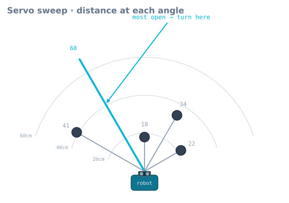
A single forward-facing distance sensor can tell a robot that something is ahead, but not which way is clear. So it turns blindly, often straight into another obstacle or a dead end. Mounting the HC-SR04 on an SG90 servo fixes this: the robot stops, looks left and right, and turns toward whichever direction is most open—the same trick a person does at a blind corner.
Why one fixed sensor traps the robot
Picture a robot that only sees straight ahead. It meets a wall, knows it must turn, but has no idea whether left or right is better. Pick wrong and it drives into the corner it just came from. A servo-mounted sensor turns one number (distance ahead) into a small map of the space around the front of the robot, so the turn is an informed choice, not a coin flip.
Mounting the sensor on the servo
Fix the HC-SR04 to the servo horn and mount the servo at the front-centre of the chassis, oriented so the horn sweeps the sensor left-to-right (not up and down). At the servo’s centre position the sensor should face dead ahead. That gives you a clean sweep from one side, through straight-on, to the other side.
Sweep and sample
Step the servo across a handful of angles and take a filtered reading at each. Reuse the clean distance function from reading the HC-SR04—a raw ping mid-sweep is far too noisy to steer on.
#include <Servo.h>
Servo scanner;

const int ANGLES[] = {30, 60, 90, 120, 150};
const int N = 5;

int bestAngle() {
  long best = -1;
  int bestA = 90;
  for (int i = 0; i < N; i++) {
    scanner.write(ANGLES[i]);
    delay(180);                 // let the servo REACH the angle first
    long d = medianCm();        // filtered read from the previous tutorial
    if (d > best) { best = d; bestA = ANGLES[i]; }
  }
  scanner.write(90);            // re-centre for driving
  return bestA;                 // > 90 = open to the left, < 90 = right
}
Don’t read mid-move
The single most common bug here is reading before the servo arrives. servo.write() returns instantly, but the SG90 takes time to swing to the new angle. Ping too soon and the distance belongs to wherever the sensor was, not where you asked it to point. A short delay after each write()—enough for the servo to settle—makes every reading trustworthy.
Turning the scan into a decision
The angle with the largest distance is the most open direction. A couple of refinements keep it sensible:
- Prefer straight ahead on ties. If two directions read similar, bias toward centre so the robot doesn’t weave needlessly.
- All directions close? That’s a dead end—back up and scan again rather than nosing further in.
Speed versus coverage
More angles give a finer picture but a slower loop, and a slow loop means the robot reacts late. Three to five angles—left, ahead, right, plus a couple in between—is the usual sweet spot. Hand that “most open” decision to the obstacle-avoidance algorithm, and try the whole behaviour in the obstacle avoidance simulator before you build it.
How long does the servo actually take?
“A short delay” is the vaguest instruction in the code above, and it is worth replacing with a number you measured. An SG90 is specified at roughly 0.1 s per 60° at 4.8 V, unloaded — so the settle time depends on how far it is travelling:
| Sweep step | Travel time (spec) | Plus settling | Use |
|---|---|---|---|
| 30° | 50 ms | ~30 ms | 80 ms |
| 60° | 100 ms | ~40 ms | 140 ms |
| 90° | 150 ms | ~40 ms | 190 ms |
| 180° (recentre from an end) | 300 ms | ~50 ms | 350 ms |
Two things make the real figure worse than the specification. Load: an HC-SR04 and its cable on the horn is small but not zero, and it slows the servo and adds overshoot. Voltage: at 4.0 V from a sagging pack, the same servo is noticeably slower than at 6 V.
Measure yours rather than trusting the table. Command a 60° step, and time how long until the distance reading stops changing:
void measureSettle() {
  scanner.write(60);  delay(500);            // known start
  scanner.write(120);                        // command the step
  const unsigned long t0 = millis();
  long prev = -1;
  for (int i = 0; i < 40; i++) {             // sample every 10 ms
    const long d = pingCm();
    Serial.print(millis() - t0); Serial.print(' '); Serial.println(d);
    delay(10);
  }
}
The reading settles at a definite moment. Use that number plus a small margin, and you have removed the largest source of nonsense from the whole behaviour.
Sweeping in one direction is faster than jumping about
The code above steps 30 → 60 → 90 → 120 → 150, which is already a single sweep, and that is deliberate. Reading angles in a scattered order means every step is a large one, and the settle cost is per step:
| Pattern | Total travel | Settle cost at ~1.7 ms/degree |
|---|---|---|
| Sweep in order (30→150) | 120° | ~200 ms plus five short settles |
| Centre-out (90, 60, 120, 30, 150) | 300° | ~510 ms |
| Return to centre between each | 480° | ~820 ms |
A full scan is a blind moment for the robot — it is stopped and not making progress — so halving its duration is a real improvement to how the robot feels. Sweep in order, and if you scan repeatedly, alternate direction so you never pay for the return trip.
Non-blocking scanning
The delay(180) in each step means a five-angle scan blocks for nearly a second. On a robot
that is stopped anyway that is tolerable, but it also means bump switches go unread and any
other behaviour is frozen.
The same state-machine treatment used for the ping applies here:
enum ScanState { SCAN_IDLE, SCAN_MOVING, SCAN_READING };

ScanState scanState = SCAN_IDLE;
uint8_t   scanIndex = 0;
unsigned long scanSince = 0;
long      scanResult[N];
bool      scanComplete = false;

void updateScan() {
  switch (scanState) {
    case SCAN_IDLE:
      break;

    case SCAN_MOVING:
      if (millis() - scanSince < SETTLE_MS) return;      // measured, above
      scanState = SCAN_READING;
      break;

    case SCAN_READING:
      scanResult[scanIndex] = medianCm();
      if (++scanIndex >= N) { scanComplete = true; scanState = SCAN_IDLE; scanner.write(90); }
      else { scanner.write(ANGLES[scanIndex]); scanSince = millis(); scanState = SCAN_MOVING; }
      break;
  }
}
The main loop calls updateScan() and carries on. Bump switches keep being read, the state
machine keeps running, and the scan completes when it completes.
Interpolating between angles
Five readings give five bearings, but the true opening is rarely exactly at one of them. A weighted centroid over the open readings gives a bearing between the samples, in the same way a reflectance array gives a line position between sensors:
// Weight each angle by how open it is, ignoring anything below the stop threshold.
float openBearing() {
  float weighted = 0, total = 0;
  for (int i = 0; i < N; i++) {
    if (scanResult[i] < STOP_CM) continue;             // blocked, contributes nothing
    const float w = scanResult[i] - STOP_CM;           // how much clearance beyond the threshold
    weighted += w * ANGLES[i];
    total    += w;
  }
  return (total > 0) ? (weighted / total) : 90.0f;     // 90 = straight ahead
}
This is a real improvement over “pick the maximum”. Taking the maximum means a doorway sampled slightly off-centre sends the robot at the doorway’s edge; the centroid sends it at the doorway’s middle. It also degrades gracefully — if two adjacent angles are both open, the result is between them rather than arbitrarily one of them.
The cone limits what a scan can tell you
An HC-SR04’s beam has roughly a 15° half-angle, which at 1 m is a cone about 53 cm across. Sampling at 30° intervals therefore overlaps heavily — adjacent readings are largely looking at the same space.
| Sample spacing | At 1 m | Consequence |
|---|---|---|
| 15° | Cones overlap almost completely | Wasted time; no new information |
| 30° | Substantial overlap | The practical sweet spot |
| 45° | Slight gaps between cones | Acceptable; can miss a narrow object |
| 60° | Real gaps | A chair leg can sit between two samples unseen |
The important consequence is that a scan does not give you angular resolution better than the beam. A reading of 68 cm at 120° means “something is 68 cm away, somewhere within about 15° of 120°” — which is fine for choosing a direction to turn, and useless for measuring the width of a gap. If you need the latter, a VL53L0X on the same servo has an effectively narrow spot and gives a genuinely resolved scan.
Troubleshooting
| Symptom | Likely cause | Fix |
|---|---|---|
| Robot turns confidently into a wall | Reading before the servo settled | Measure the settle time and use it |
| Readings smear across angles | Same, less severely | Increase the settle delay |
| Scan takes over a second | Blocking delays, or a scattered angle order | Non-blocking state machine; sweep in order |
| Board resets during a scan | Servo current through the Arduino | Separate 5 V supply, common ground |
| Robot heads for the edge of a doorway | Picking the maximum angle | Use the weighted centroid |
| Motor speed control stopped working | The Servo library takes Timer 1 (pins 9, 10) |
Move motor PWM to 3, 5, 6 or 11 |
| Servo jitters between readings | Supply noise, or software-timed pulses | Capacitor at the servo; a PCA9685 if it persists |
| A chair leg goes undetected | Sample spacing wider than the beam | 30° spacing, or a narrow-beam sensor |
| Scan is fine, robot still gets stuck | Reactive navigation has no memory | Expected — add a stuck-detector escape |
Explore the graph
Part of these builds
Projects and learning paths that include this tutorial.
Further reading