
Component · Sensor
MPU-6050 IMU
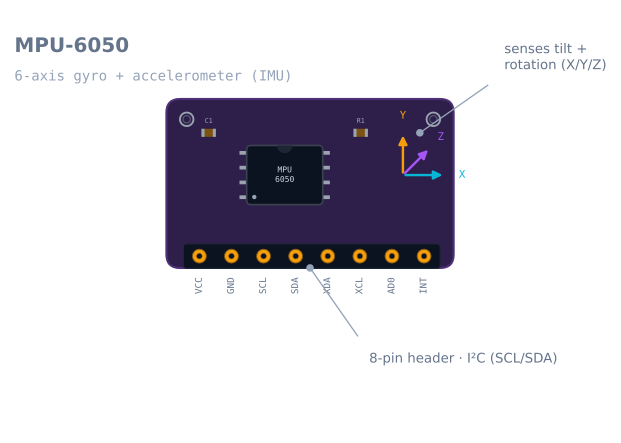
The MPU-6050 is a 6-axis IMU that senses tilt, rotation, and acceleration over I²C—how a robot knows its orientation for balancing and turning.
What it is
The MPU-6050 is how a robot feels its own motion. It is a 6-axis inertial measurement unit—a gyroscope and an accelerometer on one chip—that reports how the robot is tilted, how fast it’s spinning, and how it’s accelerating. Where an ultrasonic sensor looks outward at the world, an IMU looks inward at the robot’s own body, which is what a self-balancing robot or a dead-reckoning navigator needs.
How it works
Inside are two sensors. The accelerometer measures linear acceleration on X, Y, and Z—at rest, that’s just gravity, which tells the robot which way is down (its tilt). The gyroscope measures how fast the robot is rotating about each axis. You read both over I²C (SCL/SDA).
Neither sensor is enough alone: integrate the gyro to get an angle and it slowly drifts; trust the accelerometer and it’s noisy whenever the robot moves. The fix is sensor fusion—blend them so the accelerometer corrects the gyro’s drift and the gyro smooths the accelerometer’s noise. That technique is exactly what sensor noise, bias, and filtering covers.
When to use it
Reach for an MPU-6050 when a robot needs to know its own orientation or motion:
- Self-balancing robots — the tilt angle the control loop fights to keep at zero.
- Heading and dead reckoning — sensing turns to improve odometry between encoder readings.
- Motion detection / gestures — reacting to being picked up, tipped, or shaken.
For measuring distance to things (walls, obstacles), you want a ranging sensor like the HC-SR04 or VL53L0X instead—an IMU senses the robot, not the world.
Wiring and gotchas
- I²C, 3.3–5 V. Most breakouts (the purple GY-521) have a regulator, so 5 V is fine; the raw chip is 3.3 V only.
- Fuse the gyro and accel—don’t steer on a raw reading. A single accelerometer sample under motion is unusable as a tilt angle.
- Yaw drifts without a magnetometer; use the MPU-6050 for pitch/roll and short-term turns, not absolute compass heading.
- Keep it rigid and level-mounted; a loose sensor adds vibration the filter can’t remove.
Pinout
The purple GY-521 breakout is the board almost everyone means by “MPU-6050”. Eight pins, and four of them are usually left unconnected.
| Pin | Name | What it does | Usually |
|---|---|---|---|
| 1 | VCC | Supply. The board’s regulator accepts 3.3–5 V; the bare chip is 3.3 V only | 5 V on an Uno, 3.3 V on an ESP32 |
| 2 | GND | Ground, shared with the microcontroller | Connected |
| 3 | SCL | I²C clock | A5 on an Uno |
| 4 | SDA | I²C data | A4 on an Uno |
| 5 | XDA | Auxiliary I²C data — for a magnetometer the MPU reads on your behalf | Left open |
| 6 | XCL | Auxiliary I²C clock | Left open |
| 7 | AD0 | Address select. Low (default) = 0x68, high = 0x69 |
Left open, or tied high for a second sensor |
| 8 | INT | Interrupt out — fires on data-ready, motion, or free-fall | Left open, until you want to stop polling |
AD0 is the pin that makes two MPU-6050s on one bus possible, and it is the reason the
address collision has an easy answer here that most sensors do not offer.
Wiring it to an Arduino
| MPU-6050 | Arduino Uno | ESP32 | Note |
|---|---|---|---|
| VCC | 5 V | 3.3 V | The onboard regulator handles both |
| GND | GND | GND | Must be common with everything else |
| SCL | A5 | GPIO 22 | Do not add external pull-ups — the board has 2.2 kΩ already |
| SDA | A4 | GPIO 21 | Same |
| AD0 | — | — | Tie to VCC only for a second sensor |
There is a subtlety worth knowing on a 5 V Arduino. The GY-521’s pull-up resistors go to its regulated 3.3 V rail, so the I²C lines idle at 3.3 V, not 5 V. An ATmega328P reads high above 0.6 × Vcc = 3.0 V, so 3.3 V clears the threshold — but only by 0.3 V. It works reliably in practice and is one reason a long or noisy I²C run misbehaves on this board sooner than on a 5 V one.
Reading it: the registers that matter
You can drive this sensor with a library and never see a register, but four of them explain almost every problem people have with it.
| Register | Address | Why you care |
|---|---|---|
PWR_MGMT_1 |
0x6B |
The chip boots asleep. Write 0 here or every reading is zero |
WHO_AM_I |
0x75 |
Returns 0x68 — the fastest way to prove the wiring is right |
GYRO_CONFIG |
0x1B |
Full-scale range: ±250, ±500, ±1000, ±2000 °/s |
ACCEL_CONFIG |
0x1C |
Full-scale range: ±2, ±4, ±8, ±16 g |
ACCEL_XOUT_H |
0x3B |
Start of 14 bytes: 6 accel, 2 temperature, 6 gyro — read them in one burst |
The two config registers set the scale factor you divide raw counts by, and getting it wrong is the most common source of “my angles are four times too big”:
| Range setting | Gyro LSB per °/s | Range setting | Accel LSB per g |
|---|---|---|---|
| ±250 °/s (default) | 131 | ±2 g (default) | 16384 |
| ±500 °/s | 65.5 | ±4 g | 8192 |
| ±1000 °/s | 32.8 | ±8 g | 4096 |
| ±2000 °/s | 16.4 | ±16 g | 2048 |
Pick the smallest range that will not saturate. A balancing robot rarely exceeds ±250 °/s, and the narrow range gives four times the resolution of ±1000 °/s for free.
Minimal working code
No library — this is the whole thing, and it is worth running once so you know what the library is doing for you.
#include <Wire.h>

const uint8_t MPU = 0x68;          // 0x69 if AD0 is tied high

void setup() {
  Serial.begin(115200);
  Wire.begin();

  Wire.beginTransmission(MPU);
  Wire.write(0x6B);                 // PWR_MGMT_1
  Wire.write(0);                    // wake up — the chip boots asleep
  Wire.endTransmission(true);
}

void loop() {
  Wire.beginTransmission(MPU);
  Wire.write(0x3B);                 // ACCEL_XOUT_H
  Wire.endTransmission(false);      // repeated start, do not release the bus
  Wire.requestFrom(MPU, (uint8_t)14);

  int16_t ax = Wire.read() << 8 | Wire.read();
  int16_t ay = Wire.read() << 8 | Wire.read();
  int16_t az = Wire.read() << 8 | Wire.read();
  Wire.read(); Wire.read();         // temperature, discarded here
  int16_t gx = Wire.read() << 8 | Wire.read();
  int16_t gy = Wire.read() << 8 | Wire.read();
  int16_t gz = Wire.read() << 8 | Wire.read();

  // Default ranges: +/-2 g and +/-250 deg/s
  float pitch = atan2(ax, sqrt((float)ay * ay + (float)az * az)) * 57.2958f;
  float rateY = gy / 131.0f;        // deg/s

  Serial.print(pitch); Serial.print(' '); Serial.println(rateY);
  delay(20);
}
Two things this deliberately does not do: it never fuses the two sensors, and it never subtracts a bias. Both are next.
Calibration: the twenty lines that matter most
At rest a gyro does not read zero. It reads a small, fairly constant offset, and because you integrate the gyro to get an angle, that offset integrates into a steadily growing error. A bias of just 2 °/s left uncorrected is 120° of drift after a minute.
Average a few hundred samples with the sensor completely still, then subtract:
long sum = 0;
for (int i = 0; i < 500; i++) { sum += readGyroY(); delay(3); }
const float gyroBias = sum / 500.0f;   // subtract from every later reading
Three practical notes the datasheet will not tell you:
- Do it at every power-on, not once. Gyro bias moves with temperature, and a robot that has been running for ten minutes is not the robot you calibrated cold.
- “Still” means still. A calibration taken while the desk is being leaned on bakes that motion into the bias permanently.
- The accelerometer needs a level reference, not a zero. It should read 1 g on whichever axis points down. If it reads 0.97 g, that is your scale error, and it will show up as a tilt angle that is consistently a couple of degrees off.
Why one sensor is never enough
The two sensors fail in exactly opposite ways, which is what makes fusing them work so well.
| Accelerometer | Gyroscope | |
|---|---|---|
| Measures | Linear acceleration — at rest, gravity | Rotation rate |
| Gives you tilt by | Trigonometry on the gravity vector | Integrating rate over time |
| Short term | Noisy — every bump and vibration is acceleration too | Excellent, smooth, responsive |
| Long term | Correct on average — gravity does not drift | Drifts without bound as bias integrates |
| Fails when | The robot accelerates, so “down” is no longer down | Always, slowly |
A complementary filter takes the good half of each — trust the gyro over the short term, let the accelerometer slowly pull the estimate back toward truth:
angle = 0.98f * (angle + rate * dt) + 0.02f * accelAngle;That 0.98 sets the crossover. Higher trusts the gyro for longer, which is smoother but drifts more; lower responds to the accelerometer’s noise. The complementary filter tutorial works through how to choose it deliberately rather than by feel.
Troubleshooting
| Symptom | Likely cause | Fix |
|---|---|---|
| Every reading is exactly 0 | The chip is still asleep | Write 0 to PWR_MGMT_1 (0x6B) after Wire.begin() |
| Bus scanner finds nothing | 8-bit address from the datasheet | The datasheet’s 0xD0 is 0x68 shifted left — use 0x68 |
| Two sensors, only one appears | Both on the default address | Tie one board’s AD0 to VCC so it answers on 0x69 |
| Angles are 4× or 8× too large | Scale factor does not match the configured range | Match the divisor to GYRO_CONFIG/ACCEL_CONFIG |
| Angle drifts steadily even at rest | Uncalibrated gyro bias | Average 500 still samples at boot and subtract |
| Tilt jumps around while driving | Using the raw accelerometer angle | Fuse with the gyro; a moving robot’s “down” is not down |
| Readings freeze after a while | I²C bus locked up | Check pull-ups; add a bus-recovery routine that clocks SCL nine times |
| Heading slowly rotates forever | Yaw has no absolute reference | Expected — yaw needs a magnetometer or another absolute source |
| Noisy above about 1 kHz of vibration | Rigid mount transmitting motor vibration | Soft-mount the sensor; enable the on-chip DLPF via CONFIG (0x1A) |
MPU-6050 or something newer?
The MPU-6050 is end-of-life at the manufacturer and still the most widely used IMU in hobby robotics, because it is cheap, documented everywhere, and supported by every library.
| Part | Axes | Notable difference | Choose it when |
|---|---|---|---|
| MPU-6050 | 6 | The default; huge amount of example code | Learning, balancing, any first IMU project |
| MPU-9250 | 9 | Adds a magnetometer, so yaw has an absolute reference | You need a compass heading, not just turn rate |
| ICM-20948 | 9 | The current-production successor to the MPU-9250 | New designs that need 9 axes and long-term availability |
| BNO055 | 9 | Does the fusion on-chip and outputs orientation directly | You want an angle without writing a filter — at several times the price |
| LSM6DS3 | 6 | Modern, in production, lower noise | A drop-in upgrade when MPU-6050 supply runs out |
The honest summary: if your robot needs pitch and roll — which is what balancing needs — the MPU-6050 is entirely sufficient and the fusion is a good thing to have written yourself. If it needs absolute heading, no amount of filtering will get it from six axes, and you want a magnetometer.
Explore the graph
Used in these builds
Projects, learning paths, and simulators that include the MPU-6050 IMU.
- ProjectBuild a GPS Waypoint Rover That Drives Itself
- ProjectBuild a Mecanum Robot That Drives Sideways
- ProjectBuild a Micromouse: A Flood-Fill Maze-Solving Robot
- ProjectBuild a Self-Balancing Robot With an MPU6050 and PID
- Learning pathHolonomic Drive: Move Sideways Without Turning
- Learning pathPath Planning and Mapping: Flood Fill to SLAM
- Learning pathRobot Electronics Foundations: A Learning Roadmap
Questions
MPU-6050 IMU FAQ
What is the MPU-6050 sensor?
The MPU-6050 is a 6-axis inertial measurement unit (IMU) on a small breakout board. It combines a 3-axis gyroscope and a 3-axis accelerometer, so a robot can sense how it is tilted, how fast it is rotating, and how it is accelerating—all read over the I²C bus.
How does the MPU-6050 work?
Inside are two sensors. The accelerometer measures linear acceleration—at rest that's just gravity, which tells the robot which way is down (its tilt). The gyroscope measures rotation rate about each axis. You read both over I²C, then fuse them to get a stable orientation neither gives alone.
What is the MPU-6050 used for?
Sensing a robot's own motion—keeping a self-balancing robot upright, estimating heading and improving odometry between encoder readings, and detecting being tipped, picked up, or shaken. It senses the robot itself, not the world around it, so it complements a ranging sensor rather than replacing one.
How do you calibrate an MPU-6050?
At rest, the gyro and accelerometer read small non-zero offsets. Calibrate by averaging a few hundred samples while the sensor sits perfectly still, then subtract those offsets from every reading. The gyro especially needs this—uncalibrated bias is what makes the estimated angle drift fastest.
How do you connect an MPU-6050 to an ESP32 or Arduino?
Over I²C—wire SDA and SCL to the board's I²C pins, plus power and ground. The purple GY-521 breakout has a regulator, so it runs from 3.3 V on an ESP32 or 5 V on an Arduino Uno. A library then reads the gyroscope and accelerometer registers for you.
Further reading