
Component · Power
Robot Battery & Power Pack
How to power a robot car: why a 9V block sags under motors, choosing an AA or 18650 pack, and keeping the motor and logic rails from resetting the board.
What it is
The power pack is the part beginners think least about and get wrong most often. It is simply the battery that feeds current to the motors and the electronics—but choose it badly and the robot twitches, resets, or refuses to move, no matter how good the code is. Getting power right is often the difference between a robot that runs and one that keeps rebooting.
The key idea is that a robot has two very different appetites for current: the motors gulp it in surges, and the logic sips it steadily. One battery can feed both, but they must be arranged so the greedy motors don’t starve the sensitive brain.
How it works
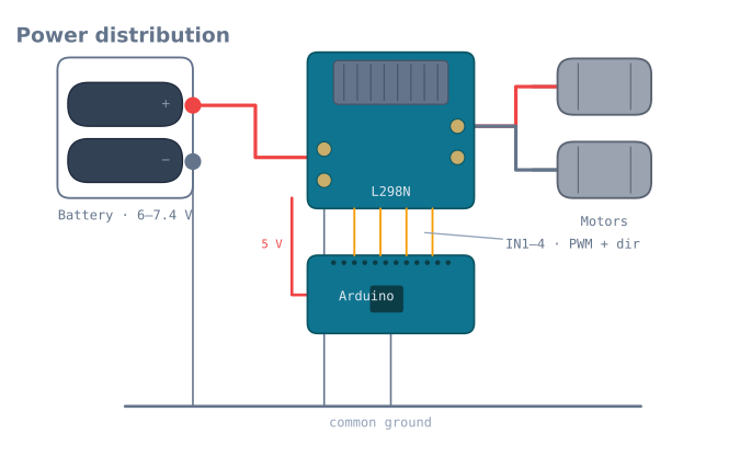
Follow the current from the pack:
- The battery supplies raw voltage—6 V from four AAs, 7.4 V from two 18650s.
- The motor rail runs straight from the pack into the L298N driver’s Vin. This is where the heavy, surging motor current comes from—kept off the Arduino entirely.
- The logic rail is a regulated 5 V (from the driver’s onboard regulator or over USB) that powers the Arduino and sensors with a clean, steady voltage.
- A common ground ties everything together. Every rail must share the same ground line, or the logic signals have no shared reference and readings become meaningless.
Split this way, a motor drawing a sudden amp can sag its own rail without dragging the Arduino’s 5 V down with it.
Why a 9 V block fails
The single most common first-robot mistake is powering the motors from a rectangular 9 V PP3 battery. It looks convenient, but it holds very little energy and has high internal resistance. The instant the motors draw current, its voltage collapses—the Arduino dips below its minimum and resets, so the robot lurches and reboots in a loop. A 9 V block is fine for a breadboard sipping milliamps; it is the wrong choice for anything that drives wheels.
Choosing and wiring
- Match voltage to the motors. 3–6 V motors are happy on a 6 V or 7.4 V pack; use PWM to tame the speed rather than under-volting the pack.
- Capacity is runtime. Higher mAh means longer between charges; 18650 cells last far longer than AAs but need a protected holder.
- One switch, correct polarity. Add a master switch on the pack and double-check polarity before first power-up—reversed power can kill a board instantly.
- Don’t back-feed. Avoid powering the Arduino from USB and the battery at the same time unless the board is designed for it.
- Add a bulk capacitor across the motor supply to soak up the start-up surge and steady the rail.
Internal resistance: the number that decides everything
Every battery behaves like an ideal voltage source with a resistor in series. That resistor is the whole story of why one pack works and another resets your board.
V_under_load = V_open_circuit - (I x R_internal)A robot pulling a 2 A surge through a pack with 0.5 Ω of internal resistance loses a full volt before anything downstream sees it. Here is what that means across the common options:
| Pack | Nominal | Typical internal resistance | Sag at 2 A | Verdict |
|---|---|---|---|---|
| 9 V PP3 alkaline | 9 V | 1.5–3 Ω | 3–6 V | Unusable for motors |
| 4×AA alkaline | 6 V | 0.6–1.2 Ω | 1.2–2.4 V | Marginal; fades fast |
| 4×AA NiMH | 4.8 V | 0.1–0.2 Ω | 0.2–0.4 V | Good, but low voltage |
| 6×AA NiMH | 7.2 V | 0.15–0.3 Ω | 0.3–0.6 V | A solid choice |
| 2×18650 Li-ion | 7.4 V | 0.05–0.15 Ω | 0.1–0.3 V | Excellent |
| 2S LiPo | 7.4 V | 0.02–0.05 Ω | Under 0.1 V | Best, with handling caveats |
This table explains the 9 V block completely. It is not that it has the wrong voltage — it has the highest voltage in the list. It is that under a 2 A surge it delivers 3 V, and the robot resets. Voltage on the shelf tells you nothing; sag under load tells you everything.
Measure yours in two minutes
1. Measure the pack's voltage with nothing connected.       -> V_open
2. Stall the motors and measure again while stalled.        -> V_load
3. Measure the stall current with the meter in series.      -> I
4. R_internal = (V_open - V_load) / I
Write the number on the pack with a marker. It rises as the cells age, and a pack whose resistance has doubled is a pack that has started causing “random” resets.
The current budget
Add it up on paper before you buy anything. Use stall, not typical.
| Device | Typical | Peak / stall |
|---|---|---|
| Arduino Uno | 45 mA | 50 mA |
| ESP32 (Wi-Fi active) | 80 mA | 500 mA in bursts |
| TT gearmotor ×2 | 300 mA | 2 A |
| N20 metal gearmotor ×2 | 200 mA | 1.6 A |
| SG90 servo | 200 mA | 650 mA |
| HC-SR04 | 15 mA | 15 mA |
| MPU-6050 | 4 mA | 4 mA |
| 8-channel IR array | 100 mA | 200 mA |
| NEO-6M GPS | 45 mA | 60 mA |
A typical obstacle-avoiding robot — Uno, two TT motors, an ultrasonic on a servo — budgets at roughly 360 mA typical and 2.7 A peak. Size the pack for the peak, and size the runtime from the typical:
runtime (hours) = capacity (mAh) / average draw (mA)2000 mAh of AA NiMH at 360 mA is about 5.5 hours of driving, which is far more than the battery in most robots ever gets used for. Capacity is rarely the constraint — surge capability is.
Wiring it properly
Battery + ──── master switch ──┬──── motor driver VM  (the heavy path)
                               │
                               └──── 5 V regulator ──── Arduino, sensors
Battery − ─────────────────────┴──── COMMON GROUND ──── everything
Four rules, in order of how often they are broken:
Common ground, always. Every supply, every board, every sensor ties to one ground. A missing common ground gives logic signals no reference, and the failure is silent — nothing works, nothing is warm, nothing looks wrong.
Star the ground, do not chain it. Run each ground back to one point rather than daisy- chaining through the motor driver. Motor return current through a shared ground wire creates a voltage difference along it, and your sensor readings shift whenever the motors move.
Master switch on the positive lead, before anything. Being able to kill a runaway robot instantly is worth the two minutes.
Reverse polarity protection. A single Schottky diode in series costs ~0.3 V, or a P-channel MOSFET costs almost nothing. Either is cheaper than the board a reversed pack destroys — and reversing a pack takes one moment of inattention.
Capacitors: what they do and do not fix
Add a 470–1000 µF electrolytic across the motor supply, close to the driver. It is worth doing. It is also routinely expected to do something it cannot.
What it does fix: the sharp switching transients from PWM and motor commutation, which are microsecond-scale and couple into the logic rail as noise.
What it cannot fix: a sustained surge. The arithmetic is unforgiving:
dV = I x t / C
1000 uF supplying 2 A for 10 ms -> dV = 2 x 0.01 / 0.001 = 20 V
A capacitor asked to carry a 2 A motor surge for 10 ms would need to drop 20 V, which is more than the pack has. Only a stiffer battery carries a surge. If your board resets when the motors start, a bigger capacitor is not the answer — a lower-internal-resistance pack is.
Do also add a 100 nF ceramic next to each IC’s supply pin. Different job entirely: it handles the high-frequency demand of the chip’s own switching, which the electrolytic is too slow to serve.
Choosing a chemistry
| NiMH AA | Li-ion 18650 | LiPo | |
|---|---|---|---|
| Cell voltage | 1.2 V | 3.7 V | 3.7 V |
| Internal resistance | Low | Very low | Lowest |
| Self-discharge | Low (use “ready to use” cells) | Very low | Very low |
| Overdischarge | Tolerant | Damaging below 3.0 V/cell | Damaging below 3.0 V/cell |
| Charging | Simple, forgiving | Needs a proper charger or BMS | Needs a balance charger |
| Fire risk | Negligible | Real if abused | Real if abused |
| Best for | A first robot | Most robots | Performance builds |
NiMH is the right first choice. Six cells give 7.2 V with low internal resistance, they tolerate mistakes, and a dead pack is an inconvenience rather than an incident.
Li-ion 18650s are the sensible upgrade: far more energy for the weight, very low internal resistance, and cheap. Use a protected holder or a BMS board — lithium cells taken below about 3.0 V per cell are permanently damaged, and a robot that runs until it stops will do exactly that.
LiPo is what performance builds use, and it is the one that requires respect. Never charge unattended, never puncture, never leave one discharged, and use a balance charger.
Troubleshooting
| Symptom | Likely cause | Fix |
|---|---|---|
| Board resets when motors start | Pack sag — internal resistance too high | Measure it; a lower-resistance pack is the only fix |
| Bigger capacitor did not help | It never could | See the arithmetic above; change the battery |
| Nothing works, nothing is warm | No common ground | Tie every ground to one point |
| Sensor readings shift when motors run | Daisy-chained ground | Star the grounds back to one point |
| Robot slows down over a run | Voltage falling as the pack drains | Expected; close a speed loop, or monitor the pack |
| Motors weak from the start | Driver voltage drop plus a sagging pack | An L298N takes ~2 V before the motors see anything |
| Regulator very hot | Too much voltage across a linear regulator | Use a switching regulator, or lower the input |
| Pack gets hot while charging | Wrong charger for the chemistry | Stop. Match the charger to the cells |
| Li-ion pack died and will not charge | Taken below 3.0 V/cell | Permanently damaged — use a protected holder next time |
Monitoring the pack
The last thing worth adding: a robot that knows its own battery voltage can stop before it browns out, and it costs two resistors.
// 100k / 33k divider: 8.4 V max in -> ~2.09 V at the pin. Safe for a 3.3 V ADC.
const float DIVIDER = (100.0 + 33.0) / 33.0;

float packVolts() {
  return analogRead(A0) * (5.0 / 1023.0) * DIVIDER;
}
One caution that makes this worth doing carefully: on an Arduino, analogRead is
ratiometric to the 5 V rail, which is itself sagging when the motors run. Measure a
falling battery through a falling reference and the reading rises. Switch to the internal
1.1 V reference with analogReference(INTERNAL), size the divider for that, and the reading
becomes honest — the
analog input tutorial covers exactly this trap.
Explore the graph
Used in these builds
Projects, learning paths, and simulators that include the Robot Battery & Power Pack.
- ProjectBuild a 4-DOF Robot Arm: PCA9685, Servos, and Kinematics
- ProjectBuild a GPS Waypoint Rover That Drives Itself
- ProjectBuild a Line Follower Robot With an 8051 Microcontroller
- ProjectBuild a Line Follower Robot: From Simulator to Real Track
- ProjectBuild a Line Maze Solver Robot With LSRB Route Memory
- ProjectBuild a Mecanum Robot That Drives Sideways
- ProjectBuild a Micromouse: A Flood-Fill Maze-Solving Robot
- ProjectBuild a Mini Sumo Robot: Grip, Wedge and Edge Sense
- ProjectBuild a Pen Plotter: Two Stepper Axes That Arrive
- ProjectBuild a Phone-Controlled Robot Car Over Bluetooth or Wi-Fi
- ProjectBuild a Pick-and-Place Robot That Knows It Missed
- ProjectBuild a Room Coverage Robot That Sweeps a Floor
- ProjectBuild a ROS 2 Robot That Sees and Drives to a Marker
- ProjectBuild a Self-Balancing Robot With an MPU6050 and PID
- ProjectBuild an Obstacle-Avoiding Robot: Sense, Scan, and Steer
- Learning pathRobot Electronics Foundations: A Learning Roadmap
Questions
Robot Battery & Power Pack FAQ
What battery should I use for an Arduino robot car?
A 4×AA pack (6 V) or a 2×18650 pack (7.4 V) feeding the motor driver is the standard choice. Both deliver the current the motors need without collapsing under load. Power the Arduino from the driver's regulated 5 V output or over USB while you develop.
Can I power a robot's motors with a 9 V battery?
Not well. A 9 V PP3 block has very little capacity and high internal resistance, so the moment the motors draw current its voltage sags and the Arduino browns out and resets. Use an AA or 18650 pack for anything with motors; save the 9 V block for a breadboard.
Do the Arduino and motors share the same battery?
They usually share one pack, but on separate rails. The motors draw from the pack through the driver's Vin terminal; the logic runs on a regulated 5 V. Critically, every supply must share a common ground, or your signals have no shared reference and nothing reads correctly.
Why does my robot reset when the motors start?
Because starting motors briefly pull a big surge of current, dipping the shared voltage below what the Arduino needs, so it reboots. Fixes are a stiffer battery, separate motor and logic rails from the same pack, and a capacitor across the motor supply to absorb the surge.
Further reading