
Component · Chassis
4-DOF Robot Arm Kit
A 4-DOF robot arm kit is the frame that turns four hobby servos into a desktop manipulator—a rotating base, shoulder, elbow, and gripper you can position.
What it is
A 4-DOF robot arm kit is the mechanical skeleton of a desktop manipulator: a set of laser-cut acrylic or aluminium brackets, a rotating base, and mounting slots for four servos. On its own it does nothing—it is the frame that turns servos into a machine that reaches, positions, and grips. Bolt in the servos, drive them with a PCA9685, and it becomes an arm you can command to a point in space.
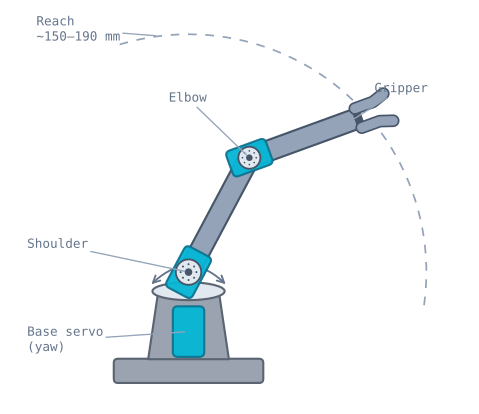
The four joints
Each degree of freedom is one servo doing one job:
- Base — rotates the whole arm left and right (yaw), aiming the working plane.
- Shoulder — lifts the upper link; the first of the two joints that set reach and height.
- Elbow — bends the forearm; together with the shoulder it places the tool anywhere in a vertical plane.
- Gripper — opens and closes the jaws to hold an object.
The shoulder and elbow are the pair that the two-link inverse kinematics solves: given a target point in the arm’s working plane, they compute the two joint angles that reach it. The base then swings that plane to the target’s direction, and the gripper does the picking.
When to use it
Reach for a 4-DOF arm kit when you want to learn manipulation rather than mobility—pick-and-place, stacking blocks, drawing, or a camera on a positionable mount. It is the arm equivalent of a 2WD chassis: the shared structure that a whole class of projects bolts onto. It is deliberately light-duty; treat it as a teaching platform, not a workhorse.
For heavier or more precise work, step up to metal-gear servos, a stiffer frame, or a 5–6 DOF arm that adds a wrist. For mobile robots, the chassis is the frame you want instead.
Wiring and gotchas
- One servo per joint, one channel each. Number the channels (0 = base, 1 = shoulder, …) and keep the map in your code so a “move the elbow” command drives the right servo.
- Power the servos separately. Four servos moving together spike the current; feed them from the PCA9685’s V+ terminal, never the Arduino.
- Home it before you assemble. Set every servo to a known angle (e.g. 90°) before pushing on the horns, so the arm’s zero pose matches your code’s zero.
- Respect the reach. The tool can only reach inside an annular ring set by the link lengths; commanding a point outside it is unreachable no matter the joint angles—see the robot arm simulator.
- Mind the leverage. Payload falls off fast as the arm extends; keep loads light or the servos stall and the nylon gears strip.
The measurements you need before writing any code
Inverse kinematics is arithmetic on link lengths. Get them wrong and the arm reaches confidently to the wrong place, with nothing in the code to blame.
| Measurement | Where to measure | Typical |
|---|---|---|
L1 — upper link |
Shoulder joint axis to elbow joint axis | 90–105 mm |
L2 — forearm |
Elbow joint axis to the gripper’s grip point | 80–95 mm |
| Base height | Table to the shoulder joint axis | 50–70 mm |
| Base offset | Base rotation axis to the shoulder axis, horizontally | 0–15 mm |
Measure between joint axes, not between bracket edges. The axis is the centre of the servo’s output spline, and it is often 5–10 mm inside the visible bracket. On a 95 mm link, a 10 mm error is over 10% — which shows up as an arm that is systematically short, and which no amount of tuning will fix.
Those two lengths give you the workspace directly:
maximum reach = L1 + L2
minimum reach = |L1 - L2|
With L1 = 100 and L2 = 90, the arm reaches between 10 mm and 190 mm from the shoulder —
an annulus, not a disc. There is a hole in the middle it physically cannot reach, and it
is a genuine surprise the first time a target near the base comes back unreachable. If the
two links are equal, the hole vanishes and the arm can fold onto itself.
Servo torque: why the arm sags at reach
The shoulder servo carries everything beyond it, and torque demand rises with how far the mass sits from the joint.
For a fully extended arm with L1 = L2 = 95 mm, holding a 30 g payload, with links weighing
roughly 20 g each:
Shoulder torque ~= (forearm+elbow mass x 0.095) + (payload x 0.190)
                ~= (0.05 kg x 9.5 cm) + (0.03 kg x 19 cm)
                ~= 0.48 + 0.57 = 1.05 kg.cm
An SG90’s stall torque is about 1.8 kg·cm at 4.8 V. Holding 1.05 kg·cm means running at 58% of stall continuously, which is well past the point where a hobby servo stays accurate — it will sag below the commanded angle, buzz, and get hot.
| Configuration | Shoulder demand | SG90 (1.8 kg·cm) | MG90S (2.2 kg·cm) |
|---|---|---|---|
| Folded, no payload | ~0.2 kg·cm | Comfortable | Comfortable |
| Extended, no payload | ~0.5 kg·cm | Fine | Fine |
| Extended, 30 g payload | ~1.05 kg·cm | Sags visibly | Marginal |
| Extended, 50 g payload | ~1.4 kg·cm | Stalls | Sags |
Three practical consequences. The arm’s accuracy is worst at full extension, which is exactly where a singularity also lives, so plan paths inside the boundary. Use metal-gear MG90S servos for the shoulder even if the rest are SG90s — it is the joint that fails first, and nylon gears strip under a sustained load. And counterbalance if you can: a rubber band from the upper link back to the base takes a surprising fraction of the static load off the shoulder servo for free.
Assembling it so the maths works
The order matters, and one step in particular is nearly impossible to undo.
1. Set every servo to its centre before fitting a horn. Power the servo, command 90°, and only then push the horn on. A servo horn is splined — around 20 or 24 teeth — so it can only be fitted in discrete positions, and the finest adjustment available is roughly 15–18°. If you assemble the arm first and calibrate afterwards, you may find a joint whose usable range is offset by 40° and cannot be corrected mechanically at all.
2. Fit the horns at the pose you want as your zero. For the shoulder, that usually means the upper link vertical. For the elbow, the forearm horizontal. Decide the convention, write it down, and build to it.
3. Check each joint’s full travel before tightening anything. Command 0° and 180° and confirm nothing collides with the frame. A joint that hits its own bracket at 160° has an effective limit of 160°, and your code must know that.
4. Record the per-joint offsets and signs. Some joints will rotate opposite to your mathematical convention because of how the linkage is arranged. Capture it once:
struct Joint {
  uint8_t channel;
  int      offsetDeg;   // servo angle when the joint is at its mathematical zero
  int8_t   sign;        // +1 or -1
  int      minDeg, maxDeg;  // mechanical limits, measured
};

const Joint BASE     = {0,  90, +1,  -85,  85};
const Joint SHOULDER = {1,  90, -1,  -10, 120};
const Joint ELBOW    = {2,  90, +1, -120,  10};
const Joint GRIPPER  = {3,  20, +1,    0,  55};

int servoAngle(const Joint &j, float jointDeg) {
  float clamped = constrain(jointDeg, j.minDeg, j.maxDeg);
  return constrain((int)(j.offsetDeg + j.sign * clamped), 0, 180);
}
That struct is the entire bridge between the kinematics and the hardware, and having it explicit is the difference between an arm you can reason about and one you keep fudging.
Powering four servos
Four micro servos moving together is well beyond what a microcontroller can supply, and the arm’s failure mode makes it worse: when the arm hits its own frame or grips something solid, every servo in the chain stalls at once.
| Situation | Current |
|---|---|
| Idle, holding position | ~40 mA total |
| Moving, unloaded | ~600 mA – 1 A |
| All four stalled | ~2.6 A |
Size the supply for the stall figure. A separate 5–6 V supply into the PCA9685’s V+ terminal, with a 470–1000 µF capacitor across it, and grounds tied to the controller. Running any of this through the Arduino’s 5 V pin will brown out the board — and because it only happens when the arm reaches a particular position, it reads convincingly as a software bug.
Move it gently
A servo commanded to a new angle goes there at full speed. On a mobile robot that is merely abrupt; on an arm it is a genuine problem: a violent movement, a current spike, and a mechanical shock through nylon gears with the arm’s own leverage multiplying it.
// Interpolate every joint together so the tool moves in a straight-ish line
// and no single servo takes the whole load at once.
void moveTo(float base, float shoulder, float elbow, int steps, int stepMs) {
  static float cur[3] = {0, 0, 0};
  float target[3] = {base, shoulder, elbow};

  for (int s = 1; s <= steps; s++) {
    float t = (float)s / steps;
    for (int j = 0; j < 3; j++) {
      float a = cur[j] + (target[j] - cur[j]) * t;
      pwm.setPWM(JOINTS[j].channel, 0, countsFor(JOINTS[j], a));
    }
    delay(stepMs);
  }
  memcpy(cur, target, sizeof(cur));
}
Interpolating all joints together matters as much as the smoothing. Moving joints one at a time sends the tool on a strange path through the workspace, which is both slower and much more likely to collide with something on the way.
Troubleshooting
| Symptom | Likely cause | Fix |
|---|---|---|
| Arm reaches the wrong point entirely | Horn fitted at an arbitrary angle | Home every servo to 90° before fitting horns |
| One joint’s range is offset by ~20° | Horn is one spline tooth out | Remove and refit — this cannot be fixed in software |
| Board resets when the arm moves | Servo current through the controller | Separate V+ supply, common ground, big capacitor |
| Arm sags at full extension | Shoulder servo past its comfortable torque | MG90S at the shoulder; counterbalance; reduce payload |
| Buzzing while holding a pose | Servo fighting a load at its limit | Reduce the load, or detach when holding is not needed |
| Reaches near the base fail | Target inside the minimum-reach annulus | Expected geometry — |L1 − L2| is unreachable |
| IK returns NaN | Target beyond L1 + L2 |
Test reachability before the trigonometry |
| Reaches differently from each direction | Gearbox backlash, amplified by link length | Approach every target from the same direction |
| Violent movement on a new command | Servo going at full speed | Interpolate the move over steps |
| Gripper crushes or drops things | No force feedback | Limit the closing angle; add foam to the jaws |
When to step up from this kit
A 4-DOF acrylic kit is a teaching platform, and it is honest about that. Its limits, in the order you will meet them:
Payload. Tens of grams. Anything heavier and the shoulder servo cannot hold it.
Repeatability. Backlash in the servo gearboxes, plus flex in acrylic links, means returning to the same commanded pose lands a few millimetres apart. Four degrees of play at the shoulder over a 190 mm reach is over 13 mm at the tool.
Wrist orientation. With four degrees of freedom you can place the tool somewhere but you cannot independently choose the angle it approaches from. A 5- or 6-DOF arm adds a wrist, which is what makes “pick this up from the side” possible.
| Upgrade | What it buys |
|---|---|
| MG90S servos throughout | Metal gears — survives shocks, less backlash |
| Aluminium links | Much less flex, better repeatability |
| MG996R servos + bigger frame | Real payload, hundreds of grams |
| 6-DOF arm | Independent tool orientation |
| Stepper- or BLDC-driven arm | Repeatability measured in tenths of a millimetre |
None of that changes the maths. The two-link kinematics you write for this kit is the same solver a better arm uses, which is precisely why the cheap frame is worth building on first.
Explore the graph
Used in these builds
Projects, learning paths, and simulators that include the 4-DOF Robot Arm Kit.
Questions
4-DOF Robot Arm Kit FAQ
What is a 4-DOF robot arm?
A 4-DOF (four degrees of freedom) robot arm has four independently controlled joints—usually a rotating base, a shoulder, an elbow, and a gripper. Those four movements let the tool reach a range of positions on a desktop and pick things up. It is the smallest arm that feels like a real manipulator while staying cheap and easy to control.
How many servos does a robot arm need?
One per joint. A 4-DOF arm uses four servos—base rotation, shoulder, elbow, and gripper. Larger arms add a wrist tilt and wrist rotate for 5 or 6 DOF. Because each servo needs its own PWM channel, arms are the classic reason to add a PCA9685 driver instead of wiring servos straight to the microcontroller.
What is the MeArm?
The MeArm is a popular open-source, laser-cut acrylic 4-DOF arm kit driven by four micro servos. It is the archetype for the cheap desktop robot arm—many kits sold today are MeArm clones or close variants. Any of them wires and codes the same way, so the kinematics and driver skills transfer between them.
How much can a hobby robot arm lift?
Not much—tens of grams at the gripper. The limit is servo torque times leverage. An SG90's ~1.8 kg·cm stall torque sounds like a lot until you spread it over a 15 cm arm, where usable payload drops to a few tens of grams. Metal-gear servos and a shorter arm help; for real lifting you need a larger, geared arm.
Do I need a PCA9685 for a robot arm?
Not strictly, but it is the right tool. Four servos will run from an Arduino's PWM pins if you power them separately, but a PCA9685 frees the microcontroller's timers, drives all the joints from two I²C pins, and routes servo current through its own supply—which is exactly what a multi-joint arm needs.
Further reading