
Tutorial · Intermediate · 25 min
Stopping at an Edge: Latency and Braking Distance
A cliff sensor buys you a fixed number of millimetres. Where they go: reaction distance you spend on latency, braking distance the floor charges you.
The budget is in millimetres, not milliseconds
A robot with a downward sensor gets one piece of information — white, now — and a fixed distance in which to act on it. A mini sumo ring gives 25 mm of border. A table edge gives whatever your sensor’s forward mounting offset happens to be. Either way it is a distance, and the robot spends it in two very different ways:
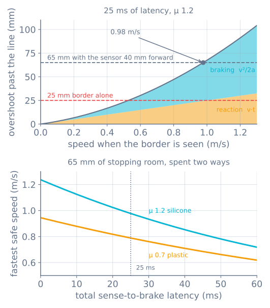
overshoot = v × t_latency + v² / (2a)The first term is bought and paid for before any braking begins. The second is what the floor charges once it does.
They behave completely differently as speed rises, and knowing which one you are paying is the difference between fixing this in an afternoon and rewriting your control loop for nothing.
Where the latency actually goes
“Latency” is not the sensor. It is everything between the photons changing and the tyres making force in the other direction, and it is nearly always dominated by a term nobody measured:
| Stage | Typical |
|---|---|
| IR emitter and phototransistor settling | ~1 ms |
| Waiting for the next pass of your loop | up to 20 ms |
| Decision and PWM write | <1 ms |
| Motor current actually reversing | ~3 ms |
| Crossing gearbox backlash before torque reaches the wheel | ~1 ms |
| Total, worst case | ~25 ms |
The loop period is four fifths of that, and it is the only line you can fix for free.
A sensor you read at 50 Hz is a sensor you are ignoring for 20 ms at a time. The usual cause is not a slow processor — it is a blocking call. One pulseIn() on an ultrasonic sensor is up to 30 ms of complete blindness, and a delay(20) for a servo is the same thing spelled differently. Reading the edge sensor every pass of a non-blocking loop costs nothing and removes most of the reaction distance.
The last row is the one that surprises people. Reversing the motors does not reverse the wheels until the gears have crossed their play, so gearbox backlash is free travel at the worst possible moment: 4° of output play on a 32 mm wheel is 1.1 mm of coasting before any braking torque arrives.
Braking is a friction problem, not a motor problem
The second term looks like it should depend on how strong the motors are. It does not.
Those same motors that can deliver 25 N of push force would decelerate a 500 g robot at 50 m/s². The floor allows µg — 11.8 m/s² on silicone, 6.9 m/s² on hard plastic. The drivetrain has four times the authority it is permitted to use, so stopping distance is set entirely by the tyres, and a bigger motor shortens it by exactly nothing.
That is why the bottom panel has two curves rather than one. At 25 ms of latency, going from plastic to silicone raises the safe speed from 0.79 to 0.98 m/s — a 24% gain from a component that also gives you 72% more push.
One honesty adjustment: µ measured by dragging a stationary robot is the static coefficient, and a hard reversal slides the wheels, which puts you on the kinetic one — typically 10–20% lower. Treat the computed speed as an optimistic bound and run at about 80% of it.
Which term dominates, and therefore what to fix
Set the two terms equal and the crossover is clean:
v × t = v² / 2a → v = 2atAt 25 ms and µ 1.2 that is 0.59 m/s.
- Below it, you are latency-bound. Halving the loop period buys more than any tyre. This is where a searching robot lives, and it is the good news: the fix is a software change.
- Above it, you are traction-bound. Grip and mass distribution matter more than loop rate, and past a point the only remaining answer is to go slower.
Most robots that fall off things are in the first regime and are being tuned as though they were in the second.
Give yourself more millimetres
The budget is not fixed. It is the border width plus the distance the sensor is mounted ahead of the wheels, and that second term is a free design variable:
budget = border + sensor leadA sensor 40 mm ahead of the drive axle turns 25 mm of border into 65 mm of stopping room, which is the difference between 0.60 m/s and 0.98 m/s. Solve it the other way when you have a target speed:
budget = v·t + v²/(2a)Practical limits on how far forward you can go:
- It has to see the border, not the ring outside it. Mounted too far forward it is looking past the line while the robot is still safe, which costs you speed for no reason.
- Mount low and shroud it. An IR reflectance sensor at 3 mm is reading the surface; at 15 mm it is reading the surface plus the room lights. This is the same threshold and calibration problem a line follower has, with a much worse failure mode.
- Put one at each front corner. A single central sensor tells you the edge is somewhere ahead. Two tell you which way to turn away from it, at no extra latency.
- Do not forget the rear. A robot being pushed backwards crosses the border going the wrong way, and the front sensors will never see it.
Reverse first, turn second
Given a fixed budget, the order of operations matters more than the tuning.
Full reverse, immediately. Not coasting — a coasting robot decelerates only at rolling resistance, which is a small fraction of µg, and the overshoot roughly triples. Not braking gently either: this is the one moment where a motion profile is the wrong instinct, because the constraint is distance rather than smoothness.
Then turn, once you have stopped. Turning while still moving forwards converts your straight-line problem into an arc that carries a corner of the robot further out than its centre. Stop first, then reorient — and remember that a pivot turn is scrubbing the tyres sideways the whole time.
Latch the detection. A single sample of white is enough. Waiting for two consecutive readings to confirm it doubles your worst-case reaction distance, and the false-positive it protects against is much cheaper than the fall.
Measuring your own latency
The number in the table is a starting estimate. Yours is measurable in about fifteen minutes.
From inside. Record micros() when the sensor crosses threshold and again on the line that writes the reversed PWM. That captures the software half, which is the half you can fix. Print the worst value seen over a hundred detections, not the average — the worst case is the one that decides whether the robot falls off.
From outside. Film it at 240 fps with a phone. Count frames between the sensor passing the line and the wheels visibly reversing; each frame is 4.2 ms. This catches the electrical and mechanical delay the software cannot see, and it is the only way to confirm the total.
End to end. Drive at a known speed at a taped line and measure how far past it the robot stops. Subtract the computed braking distance v²/2a and what remains is v × t — total latency, measured with a ruler.
The last one takes five minutes and it is worth doing before any tuning at all, because it tells you which of the two terms you are actually paying.
When it goes wrong
| Symptom | Usually |
|---|---|
| Stops reliably slow, falls off fast | Working as designed — you are past the speed the budget allows |
| Overshoots by a consistent amount | Latency; measure it end to end and shorten the loop |
| Overshoots by a variable amount | A blocking call somewhere — the loop period is not what you think |
| Sees the line late | Sensor mounted too high or too far back, or threshold set for a different room |
| Detects the border that is not there | Reflective floor or ambient IR; shroud the sensor and re-calibrate |
| Stops in time, then drives off anyway | The turn-away happened while still moving; stop first |
| Falls off backwards | No rear sensors |
The same arithmetic covers a table-edge robot, a stair-avoiding vacuum and an obstacle stop — only the budget changes. The obstacle avoidance simulator exposes exactly this stopping-distance geometry with a forward-looking sensor instead of a downward one, and the mini sumo project is where it has to work against an opponent trying to make you fail.
Explore the graph
Part of these builds
Projects and learning paths that include this tutorial.
Further reading