
Tutorial · Intermediate · 25 min
How Hard a Robot Can Push: Traction and Weight
A robot pushes as hard as friction lets it, not as hard as its motors can turn. Where those two ceilings cross, and why a wedge beats a bigger motor.
Two ceilings, and only one of them is yours
Ask how hard a robot can push and there are two answers.
The motors give one. Stall torque divided by wheel radius, times the number of driven wheels, is the largest force the drivetrain can put at the contact patch:
F_motor = n × T_stall / rThe floor gives the other. However hard the wheel pushes, friction is what actually transmits it:
F_traction = µ × NN is the weight pressing on the driven wheels. The robot can only deliver the smaller of the two, and the whole design question is which one you have hit.
Where they cross
Take a pair of 6 V metal-gearbox motors with 0.20 N·m of stall torque each, on 32 mm wheels:
F_motor = 2 × 0.20 / 0.016 = 25 NTwenty-five newtons is about 2.5 kgf — enough to shove something considerably heavier than the robot. Now set the two ceilings equal and solve for the mass where they meet:
m* = F_motor / (µ × g)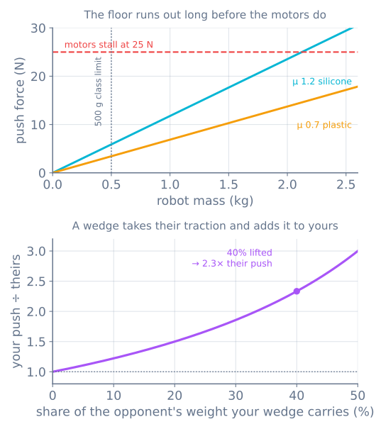
On silicone (µ ≈ 1.2) the crossover is 2.12 kg. On the hard plastic wheels a chassis kit ships with (µ ≈ 0.7) it is 3.64 kg. Both are far heavier than a small robot, and that single fact reorganises the whole build:
A hobby-weight robot is traction-limited, always. At 500 g on silicone you get 5.9 N of push out of a drivetrain capable of 25 N. Buying stronger motors changes nothing you can use.
Which is why every competition robot is built to the weight limit
Mini sumo caps a robot at 500 g in a 10 × 10 cm footprint. Read the top panel with that limit in mind and the rule stops looking arbitrary: it puts every entrant deep in the traction-limited region, where push force is linear in mass and nobody can escape by spending money on motors.
So the rule book is really saying weight is the resource, and the design consequences follow directly:
- Build to the limit. A 400 g robot is giving away 20% of its push for nothing. Ballast is a legitimate component.
- Put every gram over the driven wheels. Weight on a free-rolling castor makes no traction at all. A two-wheel robot balanced on a low-friction skid puts nearly 100% of its mass to work; the same robot on a castor at the back might be running at 65%.
- Do not add a wheel to add traction. Four driven wheels share the same total weight, so
µNis unchanged. You gain redundancy and lose nothing — but you do not gain push.
The tyre is the cheapest 70% you will ever find
The gap between the two lines in the top panel is one material choice. Silicone at µ 1.2 against hard plastic at µ 0.7 is 72% more push at the same mass, for the price of a set of tyres.
Nothing else on the robot is available at that ratio. It is worth being unreasonable about:
- Silicone or soft urethane, not the moulded plastic or hard rubber that comes in a kit.
- Clean them. Dust on the tyre is a thin layer of much lower µ, and it is why a robot that pushed fine yesterday does not today. Tape, alcohol, before every run.
- A wide contact patch does not raise µ, but it does spread the load and it wears more slowly. It also scrubs harder in a pivot turn, so this is a genuine trade.
Coefficients above 1.0 look wrong to anyone who learned that friction is capped — it is not. µ is an empirical ratio, and soft polymers on a clean hard surface really do exceed 1.
The wedge is worth more than the motors
Everything so far treats N as the robot’s own weight. A wedge that slides under the opponent breaks that assumption in two directions at once: the weight it lifts is added to your normal force and removed from theirs.
For two robots of equal mass, if your wedge carries a fraction f of the opponent’s weight:
push ratio = (1 + f) / (1 − f)The bottom panel is that curve, and it is steep:
| Lifted | Your push ÷ theirs |
|---|---|
| 0% | 1.00 |
| 20% | 1.50 |
| 40% | 2.33 |
| 50% | 3.00 |
Getting under the opponent by 40% more than doubles the mismatch, on identical motors, identical mass and identical tyres. No other change available to you comes close, which is why the front edge of a sumo robot is where the effort goes.
Making it work is a machining problem rather than a physics one:
- The leading edge has to be lower than theirs. A wedge that meets a flat plate just pushes. Thin sheet, ground to an edge, riding a fraction of a millimetre off the floor.
- It has to hold that height under load. A wedge on a flexible mount rides up over the opponent instead of under, and reverses the sign of the whole calculation.
- Symmetry costs you. Two robots with identical wedges meet edge to edge and neither lifts. The only escape is being lower, which is why this becomes an arms race measured in tenths of a millimetre.
Centre of mass: low, and forward of the axle
Two separate effects, often confused.
Low protects against being lifted. The opponent’s wedge applies an upward force at your front edge; whether that tips you or just slides under depends on how far the reaction has to travel to reach your centre of mass. A tall robot is a lever handed to the other side.
Forward loads the wedge. Push reaction acts backwards at the contact height, which transfers F × h / L from front support to rear across a wheelbase L. For a wedge pushing at 5 mm on a 70 mm wheelbase at 5.9 N, that is 0.42 N — about 43 g, and small precisely because the contact is low. It is not a mechanism to rely on, but it does mean a robot whose drive wheels sit behind the contact point gains a little grip while pushing, and one with the wheels in front loses it.
What a pushing match costs electrically
A robot pushing at its traction limit is a robot whose motors cannot turn. That is the definition of stall, and it is the most expensive state a drivetrain has:
- Stall current, sustained. Those 0.20 N·m motors draw on the order of 1.6 A each at stall, so a shoving match is ~3.2 A out of a pack that spends the rest of the round near 0.5 A.
- The rail sags exactly when you need it. This is the brown-out mechanism at its worst case, and a controller that resets mid-push has forfeited.
- All of it becomes heat. No mechanical work is leaving the motor, so every watt is I²R in the windings. Match rounds are short for good reasons.
Size the pack for stall current rather than average current, and put the motor driver selection on the same basis.
Measure it in ten minutes
Two numbers, one luggage scale, and you will know which ceiling you are under.
The traction number. Hold the robot still with the motors off, hook the scale to it and pull horizontally until it slides. The reading divided by the robot’s weight is your µ. Do it on the actual surface — a competition ring, your kitchen floor and a workshop bench are three different materials.
The motor number. Block the wheels against something immovable, command full forward, and pull backwards on the scale until the robot moves. That reading is F_motor, measured rather than interpolated from a datasheet you half trust.
Whichever is smaller is what the robot has. If they are within about 20% of each other you have a well-matched design; if traction is a quarter of the motor number, as it will be on a small robot, then every further gram, every tyre change and every millimetre of wedge is worth more than anything you can do to the drivetrain.
When it goes wrong
| Symptom | Usually |
|---|---|
| Wheels spin, robot does not move | Traction-limited — the normal answer. Add mass, change tyres |
| Motors stall dead, wheels do not spin | Motor-limited: rare, and means the gearing is too tall |
| Pushed fine yesterday, not today | Dust or oil film on the tyres; clean before every run |
| Gets pushed backwards despite winning starts | The other wedge got under yours — height, not power |
| Front lifts under push | Contact point too high for the wheelbase, or CoM too far back |
| Resets during a push | Stall current sagging the rail — see the power budget |
| Wheels spin only on acceleration | Not a push problem — a commanded step. Use a motion profile |
The consistent theme is that on a small robot the interesting numbers are all mechanical. The drivetrain has capacity to spare, and choosing the motor is a question about speed and current draw far more than it is about push.
Once the robot can push, the next constraint is being able to stop — the same coefficient of friction that sets your push force also sets your stopping distance at an edge, and the mini sumo build puts both together.
The wheel that gives up 29% before you start
One drivetrain breaks the arithmetic above, and it is worth knowing which way. A mecanum wheel can only bite along its roller’s axle, at 45° to the direction it rolls. Friction still caps the whole force vector at μN — but only the component along the rolling direction pushes the robot, so the useful force per wheel is:
F_useful ≤ μN / √2 ≈ 0.71 μNA holonomic base therefore starts a pushing match at 71% of the traction the same robot would have on plain wheels, before you account for roller rubber usually gripping worse than a tyre. And the ballast trick from earlier stops working: mass cancels out of μg/√2, so adding weight buys more grip and more inertia in exactly equal measure.
Which is the whole design decision in one line — if shoving is the point, do not buy sideways motion. Compare the drivetrains.
The same μN argument turns up again at the other end of the robot, where the contact is a fingertip rather than a tyre — and there the friction limit stops being a number and becomes a shape you can draw. That is friction, force closure and why two contacts is a bet.
Explore the graph
Part of these builds
Projects and learning paths that include this tutorial.
Further reading