
Tutorial · Intermediate · 30 min
Servo Gripper Force, Stall and Why Compliance Wins
A servo commands position; your object cares about force. The exchange rate is stiffness, and with rigid fingers the window is finer than one servo step.
A units problem, not a tuning problem
Here is the whole difficulty with a hobby-servo gripper, in two lines:
- The object cares about force. Below a floor it falls out, above a ceiling it is destroyed.
- The servo takes a position.
writeMicroseconds(1300)is an angle, and the servo will hold that angle against whatever it takes.
Those are different units, and the thing that converts between them is the series stiffness of everything between the servo horn and the object — the linkage, the finger, the pad, the object itself, all in series. If that chain has stiffness k, then driving the jaws Δc past first contact produces
N = k · Δcand the force window you have to hit, expressed in the millimetres you can actually command, is
Δc_window = ( F_ceiling − F_floor ) / kEverything in this page falls out of that one equation, including the reason a stiffer, better-printed finger makes your gripper worse.
What a servo can actually resolve
A hobby servo’s usable resolution is about one degree once you account for deadband, gear backlash and the quantisation of whatever is generating the pulse. That degree turns into jaw travel through the lever arm L:
step = L · (π/180)| Lever arm | Jaw travel per step | Stall force from an SG90 | Continuous force (≈70%) |
|---|---|---|---|
| 12 mm | 0.209 mm | 14.67 N | 10.27 N |
| 20 mm | 0.349 mm | 8.80 N | 6.16 N |
| 30 mm | 0.524 mm | 5.87 N | 4.11 N |
| 45 mm | 0.785 mm | 3.91 N | 2.74 N |
| 60 mm | 1.047 mm | 2.93 N | 2.05 N |
Two things worth noticing. A short lever arm buys both more force and finer resolution — it is better on both axes the gripper cares about. What it costs is range: jaw travel over a horn sweep of θ is just L·θ, so a 12 mm arm over 120° opens 25 mm and cannot reach round a 65 mm bottle. 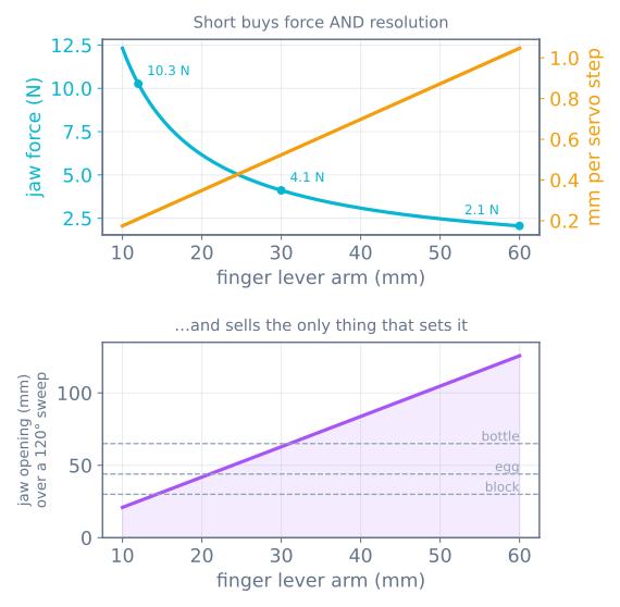
The lever arm is chosen by the largest thing you need to pick up, and force and resolution are whatever falls out of that. If you need range and force, that is what a linkage or a rack is for.
And the second thing: a PCA9685 at 12 bits gives about 0.09° of command resolution, which sounds like it fixes this. It does not. The wall is the servo’s deadband and gearbox, not the pulse source. Finer commands buy smoother motion, not finer force — the same shape as microstepping buying tracking rather than accuracy.
The window, measured
Now put the two halves together. Take a strawberry: 15 g, μ 0.6, crush around 3 N, and an SG90 on a 30 mm arm giving 4.11 N continuous. Through a 250 mm lift in 0.9 s the slip floor is 0.29 N and the ceiling is min(3, 4.11) = 3 N, so the force window is 2.71 N. Divide by the stiffness:
| Finger | k | Window | vs 0.524 mm step | Servo positions that work |
|---|---|---|---|---|
| Rigid printed PLA finger | 25 N/mm | 0.108 mm | 5× too fine | 0 |
| Rigid finger, foam pad | 4 N/mm | 0.677 mm | just wider | 1 |
| Extension spring in series | 0.8 N/mm | 3.386 mm | 6× wider | 7 |
| Printed flexure finger | 0.35 N/mm | 7.739 mm | 15× wider | 15 |
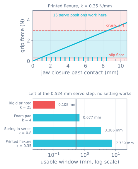
The window scales as exactly 1/k. Twenty-five over nought-point-three-five is seventy-one, and 7.739 / 0.108 is seventy-one. There is nothing approximate about it, and you can watch the two numbers move against each other by dragging the stiffness slider in the gripper simulator.
Below one servo step there is no setting that works. Not “hard to tune” — there is no command value that lands in the window, and no firmware change reaches one. This is the single most useful thing to know before printing a finger.
So why does anyone’s rigid gripper work?
Because it never lands in the window at all. It overshoots and sits pinned at the servo’s own force ceiling, and that works only while the ceiling happens to be below the object’s crush force.
Cycle the objects in the simulator with a rigid finger and the “settings that work” column is zero for every one of them — and yet four of the six are held perfectly well:
| Object | Crush limit | What happens with rigid fingers |
|---|---|---|
| Wooden block | 500 N | held — servo pinned at 4.11 N |
| M6 bolt | 2000 N | held — servo pinned |
| Chicken egg | 30 N | held — servo pinned |
| PET bottle | 8 N | held — servo pinned |
| Paper cup | 4 N | crushed |
| Strawberry | 3 N | crushed |
The servo is acting as a clutch you did not design and cannot adjust. It is set at whatever τ·0.7/L happens to be, and everything weaker than that gets destroyed.
This has a genuinely counter-intuitive consequence: fitting a bigger servo makes the gripper worse. Push the stall torque slider from an SG90 towards an MG996R and the accidental clutch moves up past the egg’s crush limit, and now you break eggs too. More torque is the wrong answer to “it drops things” almost as often as it is the right one.
The cost of holding by stalling
A servo pinned against an object is a stalled servo. It is not turning, so it is producing no mechanical power, and everything the winding draws is going into heat.
- An SG90 draws roughly 650–750 mA stalled at 4.8 V. At 70% of stall torque you are still pushing about 0.49 A through a motor with no airflow and a plastic case.
- They get hot in tens of seconds and they die in minutes. The usual symptom is a servo that works, then gets weak and jittery, then buzzes and does nothing.
- A cheap 5 V regulator supplying a couple of these will brown out, which resets your microcontroller mid-pick.
Things that fix it, roughly in order of how much they cost you:
- Don’t hold what you don’t need to hold. Open the gripper the moment the part is placed. The most common bug is a state machine that leaves the jaws closed on an empty gripper for the whole return trip.
- Back off after grasping. Close firmly, then reduce the command by a step or two. With compliance in series you keep most of the force; without it you lose all of it, which is another argument for compliance.
- Power the servo from its own supply, not the board’s regulator, with a few hundred µF nearby.
- Add a mechanical latch or an over-centre linkage for long holds. This is what production grippers do, and it draws zero current.
- Measure the case temperature with a finger after a minute of holding. Warm is fine. Too hot to keep your finger on it means you have maybe a week of duty left.
Building compliance in
Compliance is the fix for both problems at once — it opens the window and takes the servo off the stall pin. Four ways to get it, cheapest first:
A foam or TPU pad (k ≈ 4 N/mm)
Stick-on EVA foam, or a printed TPU pad 3–4 mm thick. Costs nothing, takes five minutes, and moves you from zero workable settings to about one. It is the minimum viable fix and it is not enough on its own for delicate work.
An extension spring in series (k ≈ 0.8 N/mm)
Put the spring between the servo horn and the finger, with a slot and a pin so the linkage can take up travel. Now the servo commands a spring deflection, which is a force command with real tolerance. This is a series elastic actuator built from a 40p part, and it is the best value change in the whole gripper.
The design rules: pick a spring whose working deflection covers your window (a few millimetres), preload it slightly so there is no dead zone at first contact, and add a hard stop so a runaway command cannot coil-bind it and put the full stall torque through the linkage anyway.
A printed flexure finger (k ≈ 0.35 N/mm)
A finger with a deliberately thin section that bends. Free at print time, no extra parts, and gives you the widest window of the four. Print it in PETG or nylon rather than PLA — PLA creeps under sustained load and your flexure will take a set within a few weeks of holding things.
Thickness dominates: the stiffness of a bending beam goes as thickness cubed, so 2 mm versus 1.5 mm is a factor of 2.4. Print a test strip, hang known weights off it, measure the deflection, and you have your k in ten minutes. That measured number is what belongs in the simulator, not the preset.
Fin-ray fingers
The whole finger is a truss that wraps around the object as it loads. Gives you compliance and partial form closure at the same time, which is why they have taken over hobby grippers for irregular objects. Harder to model — the effective stiffness changes as it wraps — so measure rather than calculate.
What compliance costs
It is not free, and it is worth being honest about the trade:
- Position accuracy at the object. The part ends up where the compliance put it, not where you commanded. If your task needs the part placed to 0.2 mm, compliance is working against you and you want a stiff gripper with real force sensing instead.
- Settling time. A soft finger rings after a fast move. Add a short dwell after closing before you lift, or you measure the ring instead of the grasp.
- Creep. Anything plastic under sustained load slowly deforms. Springs and PETG flexures are much better than PLA here.
- You cannot feel the object. Compliance makes the servo’s own position a worse proxy for what is going on at the fingertip, so if you want grasp detection you need a switch or a sensor — see the pick-and-place state machine.
The four numbers to have before you print
L, the lever arm — set by the widest object. Everything else follows.k, the series stiffness — measured, by hanging weights on a printed test finger.F_crush— measured, with a kitchen scale and a few sacrificial parts.step = L·(π/180)— arithmetic.
Then check (min(F_crush, τ·0.7/L) − F_floor)/k > step. If it fails, no firmware you write will make the gripper work, and the fix is always to lower k — never to raise the torque.
Next
- Friction, force closure and why two contacts is a bet — the failure that force cannot fix
- Robot gripper types and grip force — where the floor comes from
- The gripper simulator — drag stiffness and watch the window scale as 1/k
- The SG90 servo — the part this page assumes
- Driving servos with a PCA9685 — when one servo becomes six
Explore the graph
Part of these builds
Projects and learning paths that include this tutorial.
Further reading