
Tutorial · Beginner · 25 min
Bump Sensors and Debouncing for Robot Collisions
A switch closing is not one edge, it is nine. How bounce fools an interrupt, what a debounce window costs, and how to build a bumper that lasts.
A switch is not a clean edge
Press a lever microswitch and the metal contact arrives, deflects, separates, and arrives again — several times, in the first few milliseconds, before it settles. That is contact bounce, and it is mechanical: no amount of software before it and no capacitor after it makes the metal stop moving.
The consequence only matters because the pin is read by something much faster than the metal. A microcontroller sampling at 16 MHz sees every one of those transitions as a real edge.
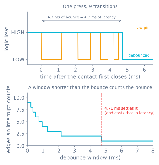
The bottom panel is the design curve. Edge count falls in steps as the window grows, hits one at the point the bounce finishes, and stays there. Anything shorter over-counts; anything longer is latency you paid for nothing.
Typical bounce durations, worth measuring rather than trusting:
| Switch | Bounce |
|---|---|
| Quality lever microswitch | 0.5–2 ms |
| Cheap tactile button | 2–10 ms |
| Reed switch | 0.1–1 ms |
| Relay contact | 1–20 ms |
The usual “5 ms is enough” advice is a guess at the middle of that table. Measure yours: it is one line of code and it turns a superstition into a number.
Wiring, before any of this matters
A bump switch wants normally-open contacts to ground, with the pin pulled up:
pinMode(BUMP_L, INPUT_PULLUP); // idle HIGH, LOW when the bumper is pressedThree reasons this arrangement rather than the other one:
- Active-low fails safe. A broken wire reads HIGH, which is not pressed, so a snapped bumper lead does not make the robot believe it is permanently colliding. A pull-down arrangement fails the other way.
- The internal pull-up is free. No resistor, no extra part on a robot whose front end is going to be hit repeatedly.
- Noise is shunted, not gathered. A long bumper wire is an antenna; the low-impedance path to ground when closed is what stops it picking up the motor driver next to it.
Use the switch’s normally-closed contact instead and you get the opposite fail behaviour — a broken wire looks like a permanent collision, which is the correct choice for an emergency stop and the wrong one for a bumper.
Debouncing: pick one of three
Ignore-after-accept. The lazy one, and correct for a bumper. Accept the first edge instantly, then refuse to look again for the window:
const unsigned long BOUNCE_MS = 6;
unsigned long lastBumpAt = 0;

bool bumped() {
  if (digitalRead(BUMP_L) == HIGH) return false;         // not pressed
  if (millis() - lastBumpAt < BOUNCE_MS) return false;   // still inside the window
  lastBumpAt = millis();
  return true;
}
Zero latency on the edge that matters, and the bounce is discarded behind it. This is what you want when the reaction is stop the motors — waiting 6 ms to be sure is 6 ms of driving into the furniture.
Wait-for-stable. The Arduino example’s approach: remember when the reading last changed and accept it only once it has held still for the window. Costs the full window in latency and is the right shape for a button on a menu, where a false press is worse than a slow one.
Hardware. A 100 nF capacitor across the contacts plus the pull-up gives an RC of about 10 ms with a 100 kΩ internal pull-up — but the edge it produces is slow, and a slow edge into a digital input can oscillate through the threshold. If you go this route, follow it with a Schmitt-trigger input. Usually not worth the parts.
Note what all three have in common: they are non-blocking. A delay(20) after the edge debounces perfectly and stops the robot reading anything else for 20 ms, which on a machine doing 0.3 m/s is 6 mm of blind travel — see timing with millis().
Interrupts and bounce are a bad pair
Attaching an interrupt to a bumper looks obviously right and usually is not.
Nine transitions means the ISR fires nine times. If it increments a counter you now have nine collisions; if it sets a flag you have one, harmlessly. Only use an interrupt if the handler is idempotent — setting a flag, capturing a timestamp — and never if it counts.
volatile bool bumpFlag = false;
volatile unsigned long bumpAt = 0;

void onBump() {                       // idempotent: nine calls do what one call does
  if (millis() - bumpAt < BOUNCE_MS) return;
  bumpAt = millis();
  bumpFlag = true;
}
millis() does not advance inside an ISR on an AVR, which makes this safe for the duration of one bounce but wrong for anything longer — use micros() if the window matters precisely.
Honestly, for a bumper you rarely need the interrupt at all. A loop running at 200 Hz notices a collision within 5 ms, and the robot travels 1.5 mm in that time. Poll it, and spend the interrupt pins on the encoders that genuinely cannot be polled.
Building a bumper that works
The switch is the easy half. The mechanism in front of it decides whether the robot detects a chair leg it hits at an angle.
- One moving shell, two switches. A single front panel on two flexure points, with a switch behind each side. Left switch alone means the obstacle is to the left, which is the information the avoidance behaviour needs to choose which way to turn.
- Wrap it round the corners. A flat front bumper misses anything hit at more than about 30°, and glancing hits are most of them. Take the shell round to at least 45° each side.
- Springs return it, switches do not. A microswitch’s own spring is 50–100 g and will not push a shell back reliably. Use rubber bands or light compression springs, and let the switch only sense.
- Give it travel and a hard stop. 3–5 mm of movement before the switch actuates, and a stop that takes the impact instead of the switch body. Switch bodies are the thing that breaks.
- Pair it with something non-contact. A bumper is a last resort — it reports a collision that already happened. An ultrasonic or time-of-flight sensor in front of it is what avoids most of them; the bumper catches the black chair leg, the glass, and the thing at the wrong height.
Measuring your own bounce
// Count transitions in the 20 ms after the first edge. Run it, press the switch,
// read the number. That number is your debounce window, in your robot, with your wiring.
void loop() {
  if (digitalRead(BUMP_L) == HIGH) return;
  unsigned long start = micros();
  int last = LOW, edges = 0;
  while (micros() - start < 20000) {
    int now = digitalRead(BUMP_L);
    if (now != last) { edges++; last = now; lastEdgeAt = micros(); }
  }
  Serial.print(edges); Serial.print(" edges, settled after ");
  Serial.print(lastEdgeAt - start); Serial.println(" us");
  delay(500);
}
Set the window to the settling time you measure, plus about 50%. Re-measure when the switch is old — contacts get worse, not better.
When it goes wrong
| Symptom | Usually |
|---|---|
| One bump counted as several | No debounce, or a window shorter than the bounce |
| Bumps missed entirely | Blocking call somewhere; the loop was not looking |
| Robot reverses at random | Long unshielded bumper wire near the motor driver |
| Reports a permanent collision | Broken wire on a normally-closed contact, or no pull-up |
| Detects head-on hits only | Bumper shell too flat — wrap it round the corners |
| Switch stops working after a week | The switch body took the impact instead of a hard stop |
| Detects the wall but not the chair leg | Nothing wrong with the switch; the shell has a gap |
For where a bumper sits in a whole robot, the room coverage robot is built on two of them and nothing else — and the coverage simulator shows exactly how far a robot gets on one bit of sensing.
Explore the graph
Part of these builds
Projects and learning paths that include this tutorial.
Further reading