
Component · Actuator
N20 Encoder Gearmotor
The N20 is a small metal-gearbox motor with a built-in magnetic encoder, the usual drive choice for balancing robots that need torque and wheel position.
What it is
The N20 is the small metal-gearbox motor that shows up wherever a robot needs real torque in very little space. The bare motor is about the size of an AA battery; the gearbox on the front trades its very high speed for usable torque, and on the encoder version a magnetic disc on the rear shaft reports how far it has turned.
That last part is what earns it a place in a balancing robot. Without wheel feedback, a balancing robot can stay upright but has no idea where it is — it will hold vertical beautifully while wandering across the room. The encoder closes that gap.
Why the metal gearbox matters here
A plastic-gearbox motor like the TT gearmotor is perfectly good for a line follower, which mostly drives forwards. A balancing robot is a different load: it reverses direction continuously, hundreds of times a second, in small increments.
Every gearbox has backlash — a small dead zone where the gears have disengaged and the output does not move until the teeth meet again on the other side. In a plastic gearbox that dead zone is large, and in a balancing robot it lands exactly where the correction matters most: at the moment of reversal, when the robot needs the wheels to respond now. The result is a robot that oscillates around vertical and never quite settles, no matter how carefully the gains are tuned.
Metal gears do not remove backlash but reduce it enough that the loop can do its job. How much is left is a number you can measure in about ten minutes — here is how.
Reading the encoder
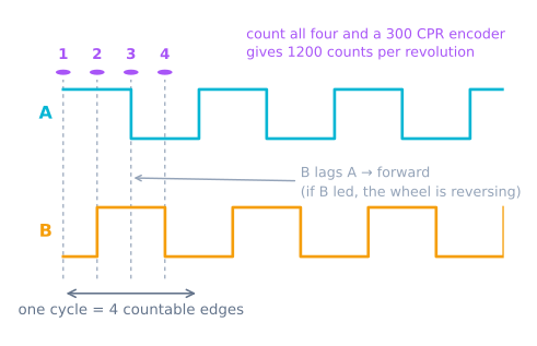
The encoder produces two square waves 90° out of phase — standard quadrature. The phase relationship tells you direction; counting edges tells you distance.
| Wire (typical) | Connects to | Notes |
|---|---|---|
M1, M2 |
Motor driver outputs | The motor itself; polarity sets direction |
VCC |
3.3 V or 5 V | Encoder supply, not the motor supply |
GND |
Ground | Common with the controller |
C1 |
Interrupt-capable pin | Encoder channel A |
C2 |
Any digital pin | Encoder channel B |
Wire colours vary between suppliers, so check the listing rather than assuming. The one that catches people out is powering the encoder from the motor rail: the encoder wants a clean logic supply, and feeding it the motor voltage will either destroy it or fill your counts with noise every time the motor switches.
Put channel A on a pin that can raise an interrupt. Polling an encoder from loop() on a balancing robot will drop counts, and dropped counts mean the outer loop slowly loses track of where the robot is.
Choosing a ratio
The gear ratio sets the trade between torque and speed, and a balancing robot needs both:
- Too high a ratio (1:250 and up) gives ample torque but the wheels cannot spin up fast enough to get back under a falling body.
- Too low a ratio (1:30 and below) spins quickly but cannot move the robot’s mass with authority.
Around 1:100 at 12 V — roughly 200 RPM — is a reliable starting point for a small robot. If yours catches itself from small disturbances but loses bigger ones, you likely need more speed, not more gain.
Driving it
Pair the N20 with a TB6612FNG rather than an L298N. The reason is dropout: the L298N loses roughly 2 V across its output stage, so a large part of your battery never reaches the motor, and small correction commands fall below the voltage at which the motor moves at all. On a balancing robot that dead zone sits right where the fine corrections live.
Power it from a battery pack that can supply the stall current of both motors at once without its voltage sagging — a sagging rail resets the microcontroller mid-correction, and the robot falls over for reasons that have nothing to do with your control loop.
Working out counts per wheel revolution
This is the number every distance calculation depends on, and it is the one people most often get wrong — usually by a factor of four.
counts per wheel revolution = PPR x 4 x gear ratioThe magnetic encoder gives 7 pulses per motor revolution on each channel. Quadrature means two channels 90° apart, which produces four countable edges per pulse cycle. And the gearbox means the motor turns many times per wheel turn.
| Gear ratio | Counts per wheel revolution (×4) | Resolution on a 43 mm wheel |
|---|---|---|
| 1:30 | 840 | 0.16 mm |
| 1:50 | 1400 | 0.10 mm |
| 1:100 | 2800 | 0.048 mm |
| 1:150 | 4200 | 0.032 mm |
| 1:298 | 8344 | 0.016 mm |
Then distance follows directly:
mm per count = (pi x wheel_diameter_mm) / counts_per_revolutionTwo traps live in that first formula. The ×4 is only correct if you actually count four edges — both edges on both channels. Plenty of example code counts rising edges on channel A only, which is ×1, and using a ×4 constant with ×1 counting puts every distance out by exactly four. And the gear ratio printed on the motor is often approximate: a “1:100” N20 is frequently 1:99.5 or 1:100.37. For odometry over any distance, calibrate empirically instead: push the robot exactly 2 m and divide.
Counting the edges without dropping any
At 200 RPM through a 1:100 gearbox, the motor shaft turns 20000 RPM, giving
20000/60 × 7 × 4 ≈ 9300 edges per second per motor. Two motors is nearly 19000 interrupts
per second, and that is at full speed with no load.
The interrupt handler has to be genuinely small:
volatile long countL = 0;

// Full x4 decoding, table-driven. Both channels, both edges.
const int8_t QUAD_TABLE[16] = {0,-1,1,0, 1,0,0,-1, -1,0,0,1, 0,1,-1,0};
volatile uint8_t prevL = 0;

void isrLeft() {
  uint8_t now = (digitalRead(ENC_L_A) << 1) | digitalRead(ENC_L_B);
  countL += QUAD_TABLE[(prevL << 2) | now];
  prevL = now;
}

void setup() {
  pinMode(ENC_L_A, INPUT_PULLUP);
  pinMode(ENC_L_B, INPUT_PULLUP);
  attachInterrupt(digitalPinToInterrupt(ENC_L_A), isrLeft, CHANGE);
  attachInterrupt(digitalPinToInterrupt(ENC_L_B), isrLeft, CHANGE);
}

long readCount() {           // long is not atomic on an 8-bit AVR
  noInterrupts();
  long v = countL;
  interrupts();
  return v;
}
Three details that matter:
volatile, and an atomic read. A long is four bytes on an AVR, read one byte at a time.
An interrupt landing mid-read gives you a value that is half old and half new — which produces
an occasional enormous jump in your odometry, at random, roughly once in a few thousand reads.
The lookup table decodes the transition rather than guessing direction from one channel. It also naturally rejects invalid transitions (both bits changing at once, which means you missed one) by contributing zero.
Pin pressure. Full ×4 decoding on two motors needs four interrupt-capable pins, and an
Arduino Uno has exactly two. The options are: use ×2 decoding (one channel per motor,
CHANGE), which halves resolution and still gives direction; move to a board with more
interrupt pins such as a Mega or an ESP32; or use pin-change interrupts, which every AVR pin
supports but which require handling a whole port at once.
Speed from counts
Position is a count. Speed needs a difference over time, and how you take it decides whether your control loop is usable.
long lastCount = 0;
unsigned long lastMicros = 0;

float speedMmPerSec() {
  long   c  = readCount();
  unsigned long t = micros();

  float dt = (t - lastMicros) * 1e-6f;
  if (dt < 0.005f) return lastSpeed;        // too short: quantisation dominates

  float mm = (c - lastCount) * MM_PER_COUNT;
  lastCount = c; lastMicros = t;

  lastSpeed = mm / dt;
  return lastSpeed;
}
The dt guard is the important line. Sample too fast and you are dividing a difference of one
or two counts by a tiny interval, so the quantisation error dominates and the “speed” is
mostly noise — which a derivative term in a PID loop will then amplify enthusiastically.
There are two honest ways to measure speed from an encoder, and they suit different ends of the range. Counting edges in a fixed window (the code above) is good at high speed and poor at low speed, where few edges arrive per window. Timing the interval between edges is the reverse: excellent at low speed, noisy at high speed. A robot that needs both ends usually switches between them at a threshold.
Troubleshooting
| Symptom | Likely cause | Fix |
|---|---|---|
| Counts are 4× too small | Counting one edge, using a ×4 constant | Decode all four edges, or fix the constant |
| Counts increase in both directions | Only reading one channel | Quadrature needs both — use the table decoder |
| Occasional huge jump in position | Non-atomic read of a long |
Wrap the read in noInterrupts() |
| Counts drift when the motor is stopped | Electrical noise on the encoder lines | Encoder on a clean supply, not the motor rail; twist the pair |
| Counts lost at high speed | Interrupt handler too slow, or polling | Keep the ISR tiny; never poll |
| Distances consistently 2–3% out | Nominal gear ratio and wheel diameter | Calibrate over 2 m and derive mm-per-count |
| One wheel counts, the other does not | Encoder channel not on an interrupt pin | Check pin capability; an Uno has only D2 and D3 |
| Encoder died after wiring | Motor voltage into the encoder VCC | The encoder wants 3.3–5 V logic, never the motor rail |
| Robot’s position drifts over a long run | Odometry is unbounded by nature | Expected — correct it with an absolute reference |
N20 or TT gearmotor?
| TT gearmotor | N20 metal gearmotor | |
|---|---|---|
| Gearbox | Plastic | Metal |
| Backlash | Large — several degrees at the output | Small |
| Size | Bulky | About an AA battery |
| Voltage | 3–6 V | 6–12 V variants |
| Ratios available | Essentially one (~1:48) | 1:30 to 1:298 |
| Encoder | Aftermarket, awkward | Integral magnetic, standard |
| Cost | ~$2 | ~$8 |
| Best for | Line followers, first robots | Balancing, precise odometry, tight spaces |
The deciding factor is rarely torque and almost always backlash and feedback. A line follower drives mostly forwards and steers by a sensor that looks at the floor — it never notices gearbox play, and a TT motor is the right, cheap answer. A balancing robot reverses direction hundreds of times a second in tiny increments, so the dead zone at every reversal is exactly where its correction needs to act, and plastic gears make the loop unstable no matter how it is tuned.
The same logic applies to a maze solver: it navigates by counting distance, so lost motion at every turn accumulates directly into position error.
Used in
- Self-balancing robot — the drive motors, with the encoders feeding the outer position loop
Explore the graph
Used in these builds
Projects, learning paths, and simulators that include the N20 Encoder Gearmotor.
- ProjectBuild a GPS Waypoint Rover That Drives Itself
- ProjectBuild a Mecanum Robot That Drives Sideways
- ProjectBuild a Micromouse: A Flood-Fill Maze-Solving Robot
- ProjectBuild a Mini Sumo Robot: Grip, Wedge and Edge Sense
- ProjectBuild a Room Coverage Robot That Sweeps a Floor
- ProjectBuild a ROS 2 Robot That Sees and Drives to a Marker
- ProjectBuild a Self-Balancing Robot With an MPU6050 and PID
- Learning pathHolonomic Drive: Move Sideways Without Turning
Compare
Alternatives
Questions
N20 Encoder Gearmotor FAQ
What is an N20 encoder motor?
An N20 is a micro gearmotor about 12 by 10 by 26 mm with a metal gearbox, and the encoder version adds a small magnetic disc and sensor on the rear of the motor shaft. The gearbox gives it far more torque than its size suggests, and the encoder reports how far the shaft has actually turned rather than how far you asked it to turn.
Why do balancing robots use N20 motors instead of TT motors?
Two reasons. The metal gearbox has much less backlash than the plastic gearbox in a TT motor, and backlash is poison to a balancing robot—every time the motor reverses, a loose gearbox wastes the first few degrees of correction doing nothing. The encoder also gives the outer control loop real wheel position, which is what lets the robot hold a spot instead of drifting.
How many encoder counts does an N20 give per wheel revolution?
Multiply the motor-shaft pulses by the gear ratio. A typical encoder gives 7 pulses per motor revolution per channel; on a 1:100 gearbox that is 700 pulses per output revolution, or 2800 counts if you decode all four quadrature edges. Always confirm the figure for your specific motor, because both the pulse count and the exact ratio vary between suppliers.
Can I drive an N20 straight from an Arduino pin?
No. An N20 draws several hundred milliamps running and around 700 mA stalled, well beyond what a pin can supply, and the inductive kickback will damage it. Use a motor driver such as the TB6612FNG, which also has a low enough voltage drop that small correction commands still actually move the motor.
What gear ratio should I pick for a balancing robot?
Something in the 1:50 to 1:150 range is the usual compromise. Too high a ratio gives plenty of torque but the wheels cannot accelerate quickly enough to catch a fall; too low and the motor lacks the torque to move the robot's mass at all. Around 1:100 at 12 V, giving roughly 200 RPM, suits a typical small balancing robot.
Further reading